
Robot control device, robot system, and robot

a robot control and robot technology, applied in the field of robot control devices, a robot system, and a robot, can solve the problems of unintentional contact between the hand that grips the object and the object, the burden of calibration is relieved, and the precision is not secured

Active Publication Date: 2015-04-30
SEIKO EPSON CORP
View PDF6 Cites 22 Cited by
  • Summary
  • Abstract
  • Description
  • Claims
  • Application Information

AI Technical Summary

Benefits of technology

The invention provides a robot control system that can reduce unintended contact with objects and prevent damage to hands. This is achieved while alleviating burdens related to calibration.

Problems solved by technology

However, when the calibration is not performed or when the calibration performed is insufficient, in the methods described in JP-A-2011-93055 and JP-A-2010-137299, precision is not secured due to a position and a posture in which the robot is installed, as well as other factors.
Therefore, there is a concern that a hand that grips the object comes into contact with the object unintentionally or the object or the hand itself is damaged.
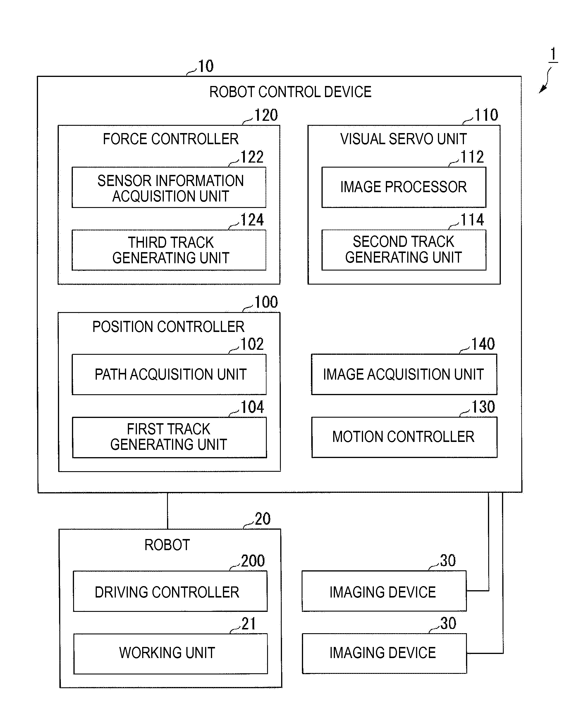
The robot control device includes an image acquisition unit that acquires an image including an object, and a controller that starts a visual servo on the basis of at least one of an error in calibration, an error in installation of the robot, an error resulting from the rigidity of the robot, an error of a position where the robot has gripped the object, an error regarding imaging, and an error regarding a work environment.

Method used


Image

  • Robot control device, robot system, and robot
  • Robot control device, robot system, and robot
  • Robot control device, robot system, and robot

Examples


Embodiment Construction

[0061]Hereinafter, embodiments of the invention will be described referring to the drawings.

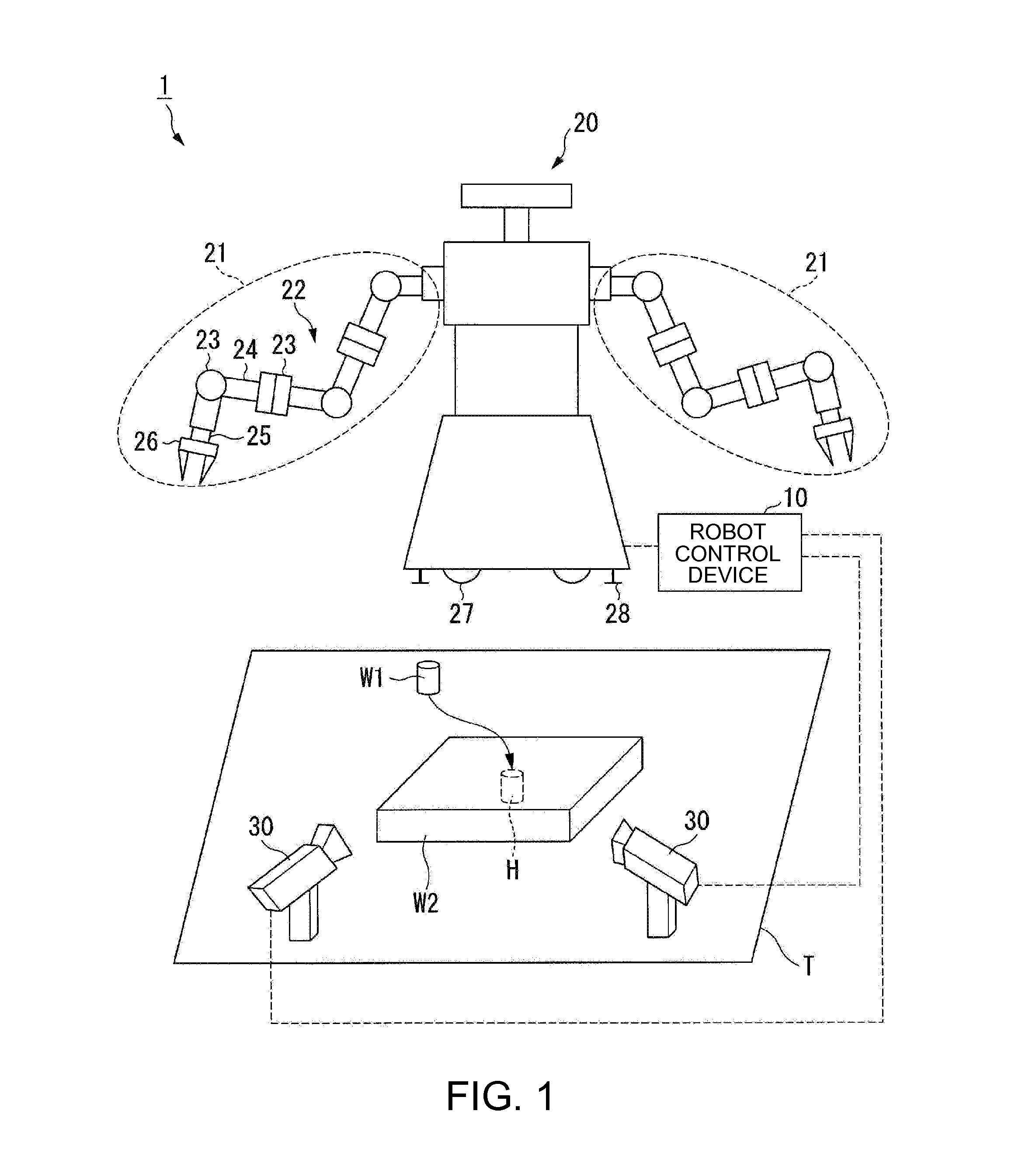
[0062]FIG. 1 is a schematic view of a robot system 1 according to the present embodiment.

[0063]The robot system 1 includes a robot control device 10, a robot 20, and one or a plurality of (two in this example) imaging devices 30. The robot control device 10 is connected to the robot 20 and each imaging device 30 so as to be communicable therewith.

[0064]The robot control device 10 controls the motion of the robot 20. The robot control device 10, for example, performs the control of acquiring image data showing images including an object serving as a work object of the robot 20 from the imaging device 30, and starting a visual servo based on the acquired images to bring the position of the object close to a target position. The conditions under which the visual servo is started can be set in advance on the basis of at least one of an error in calibration, an error in installation of the robot 2...


PUM


Abstract

An image acquisition unit acquires an image including an object, and a controller starts a visual servo using the acquired image, on the basis of at least one of an error in calibration, an error in installation of a robot, an error resulting from the rigidity of the robot, an error of a position where the robot has gripped the object, an error regarding imaging, and an error regarding a work environment. Additionally, the controller starts the visual servo when the distance between one point of a working unit of the robot and the object is equal to or greater than 2 mm.

Description

BACKGROUND[0001]1. Technical Field[0002]The present invention relates to a robot control device, a robot system, and a robot.[0003]2. Related Art[0004]In working sites for manufacturing or the like, multiaxial robots have been used for work, such as assembly, inspection, or the like of products, and work traditionally performed by human hands has been automated. When components, such as hands constituting parts of the robots, are actuated, the position and posture thereof requires precision according to the respective work. Thus, calibration is performed in advance in a work environment to acquire the position of a reference point. In the related art, the calibration is strictly performed primarily by human hands. For example, in order to secure a precision of 0.02 mm, several hours to more than a day have been spent only for the calibration.[0005]Here, the work as described in JP-A-2011-93055 and JP-A-2010-137299 is performed after the calibration is strictly performed.[0006]For ex...

Claims


Application Information

Patent Timeline
IPC IPC(8): B25J9/16
CPCB25J9/1697Y10S901/03Y10S901/47G05B2219/39016G05B2219/39391G05B2219/39394
Inventor MIYAZAWA, HIROSHIYAMAGUCHI, YUKIHIROKARITO, NOBUHIRO
Owner SEIKO EPSON CORP
Learn More