
Filter structure of infrared touch module

a filter structure and infrared touch technology, applied in the field of infrared filter structure, can solve the problems of circuit or electronic components of the second circuit board b>17/b> being damaged, and achieve the effects of preventing displacing or detaching, preventing damage, and securely attaching

Inactive Publication Date: 2015-02-26
ASIA VITAL COMPONENTS SHENZHEN CO LTD
View PDF4 Cites 6 Cited by
  • Summary
  • Abstract
  • Description
  • Claims
  • Application Information

AI Technical Summary

Benefits of technology

The present invention provides a filter structure for an infrared touch module that is more securely attached to the transparent panel and prevented from displacing or detaching from the transparent panel. The filter structure has an extension section that extends to a position between the transparent panel and a circuit board. This prevents the circuit board from being damaged when separating the circuit board from the transparent panel. The technical effects of this invention are that it improves the reliability and re-workability of the infrared touch module.

Problems solved by technology

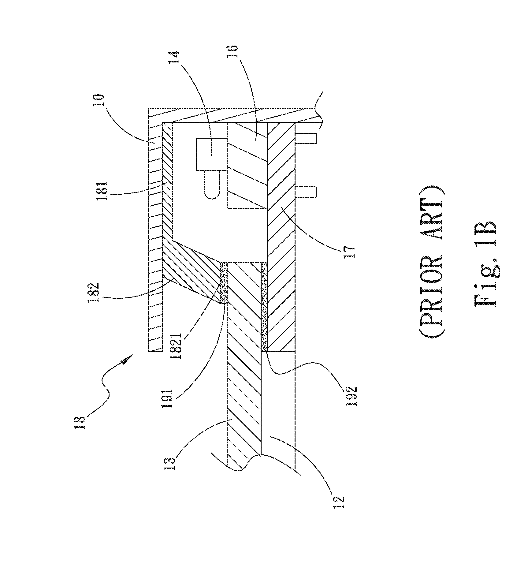
Under such circumstance, the circuit or electronic components of the second circuit board 17 may be damaged.

Method used


Image

  • Filter structure of infrared touch module
  • Filter structure of infrared touch module
  • Filter structure of infrared touch module

Examples


Embodiment Construction

[0029]The embodiments of the present invention will be described hereinafter with reference to the drawings, wherein the same components are denoted with the same reference numerals.

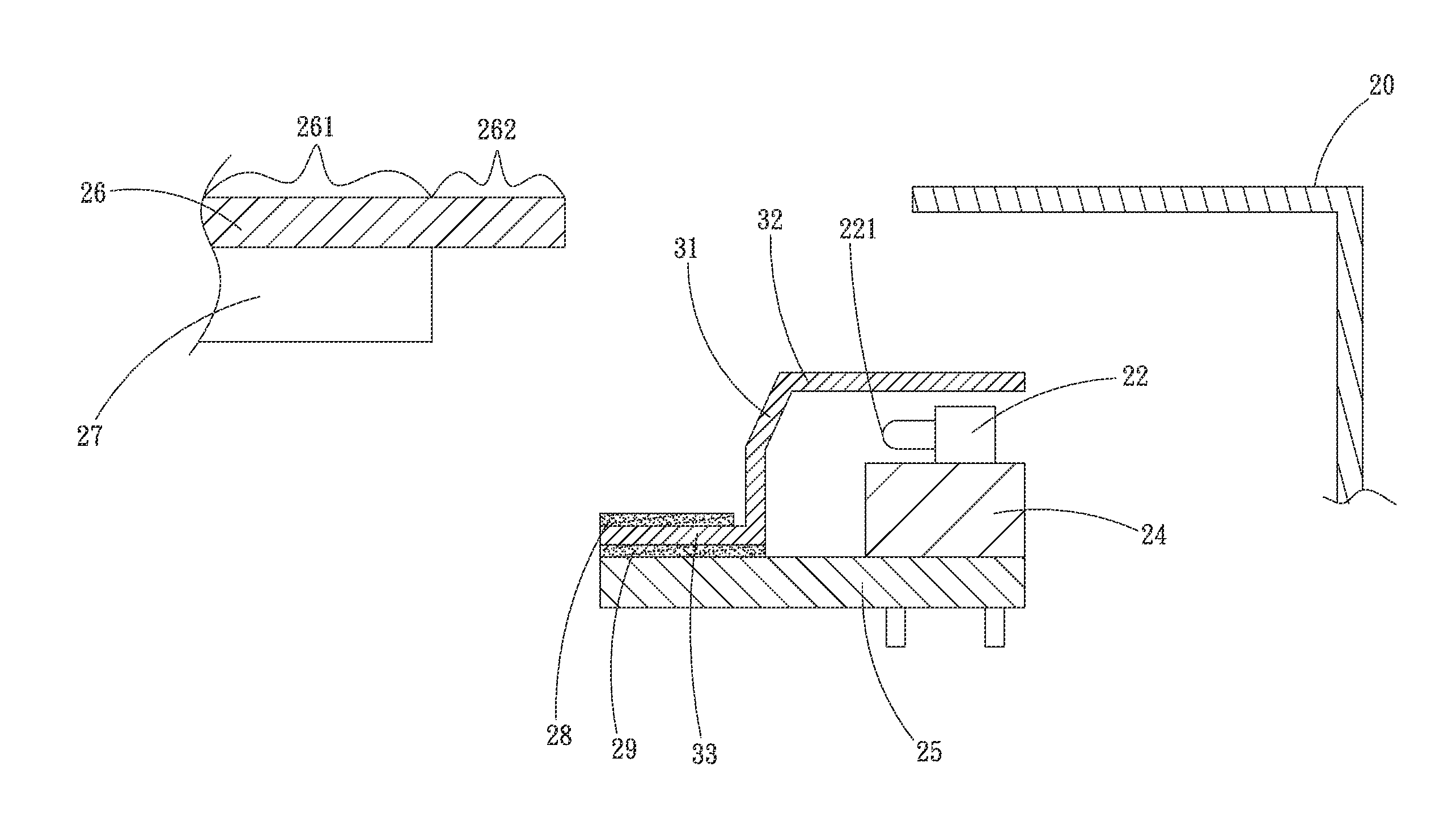
[0030]Please refer to FIGS. 2, 3A and 3B. FIG. 2 is a top view of the infrared touch module of the present invention. FIG. 3A is a sectional view of the first embodiment of the filter structure of the present invention. FIG. 3B is a sectional view showing that the first embodiment of the filter structure of the present invention is applied to an infrared touch module.

[0031]As shown in FIG. 2, a side frame 20 defines a window 21 therein. Two sets of corresponding infrared transmitters 22 and infrared receivers 23 are arranged on the opposite sides of the frame body 20. The infrared transmitters 22 and infrared receivers 23 are disposed on a first circuit board 24 (as shown in FIG. 3B). The first circuit board 24 is electrically connected with a second circuit board 25 (as shown in FIG. 3B). The first circ...


PUM


Abstract

A filter structure of infrared touch module includes a main body having an upper protrusion section and an extension section. The upper protrusion section and the extension section respectively extend from an upper end and a lower end of the main body in reverse directions. The upper protrusion section extends to upper sides of multiple infrared transmitters and multiple infrared receivers. The main body is positioned in front of the transmission faces of the infrared transmitters and the receiving faces of the infrared receivers to shield the transmission faces and the receiving faces. The extension section extends to a position between a transparent panel and a second circuit board.

Description

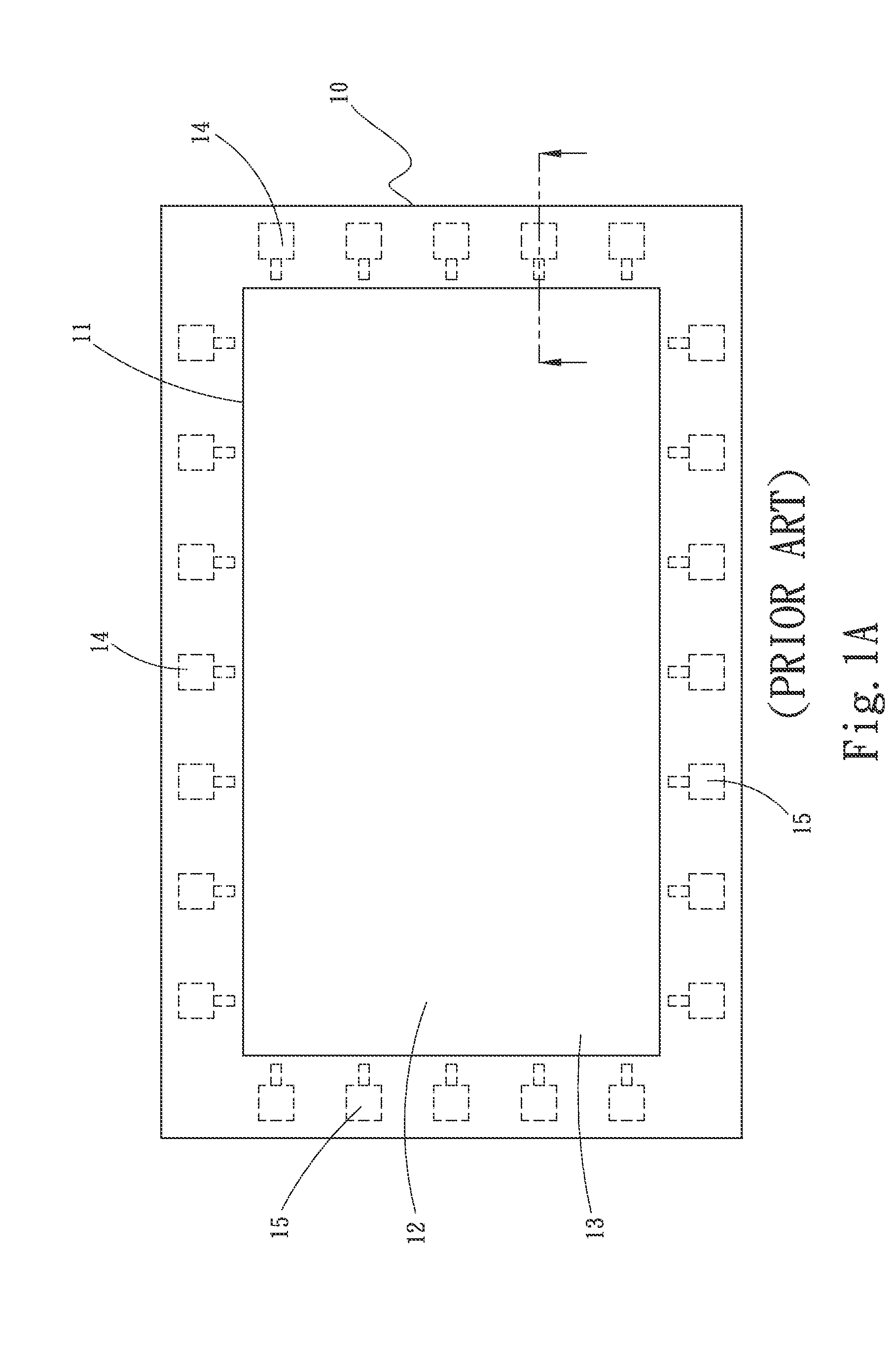
BACKGROUND OF THE INVENTION[0001]1. Field of the Invention[0002]The present invention relates generally to an infrared filter structure, and more particularly to a filter structure applied to infrared touch module.[0003]2. Description of the Related Art[0004]Infrared touch technique has the advantages of high transparency, sensitivity to the touch of any material and applicability to large-size display. Therefore, infrared touch technique is widely applied to various displays. An infrared touch display screen has infrared transmitters and infrared receivers correspondingly arranged on opposite sides of the surface of the display screen. The infrared transmitters and infrared receivers form an infrared network densely distributed over the surface of the display screen. In touch, the article (such as a finger) will partially interrupt the infrared network to calculate the touch position.[0005]The infrared touch display screen necessitates an infrared transparent frame to ensure that t...

Claims


Application Information

Patent Timeline
Patent Type & Authority Applications(United States)
IPC IPC(8): G06F3/042
CPCG06F3/0421G06F1/1609
Inventor CHANG, CHIH-WEI
Owner ASIA VITAL COMPONENTS SHENZHEN CO LTD
Learn More