
Appliance control panel assembly

Active Publication Date: 2015-02-12
ELECTROLUX APPLIANCES
View PDF27 Cites 10 Cited by
  • Summary
  • Abstract
  • Description
  • Claims
  • Application Information

AI Technical Summary

Benefits of technology

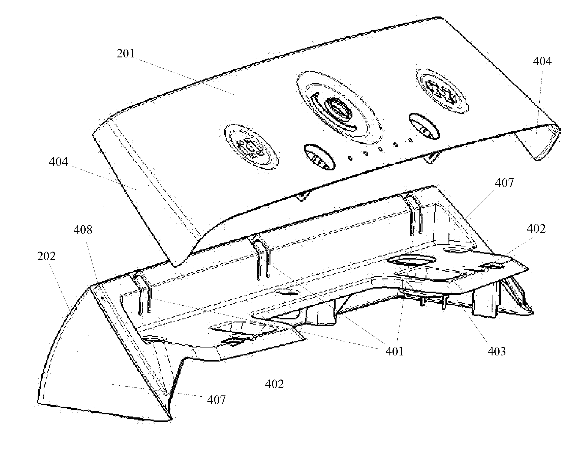
The patent describes a control panel that can be easily disassembled for maintenance or replacement. The control panel is made up of a flexible hook that is attached to a hook seat. The hook can be freed from the hook seat by inserting a long thin object into a hole, allowing the upper part of the control panel to be easily slid off the angled base part. This disassembly process can be done with one hand, and without having to move the entire appliance. The technical effect of this invention is that it provides a simple and easy way to disassemble the control panel for maintenance or replacement.

Problems solved by technology

Routine maintenance or diagnosing problems with the laundry machine may require removal of the control panel.
The amount of time and expertise required to safely remove the control panel of many appliances may be problematic due to their permanent attachment.
Even in appliances without permanently attached control panels, removing a control panel may be difficult.
Wiring connecting the appliance to the instrumentality on the control panel is often difficult to work around and may have to be removed prior to maintenance, especially if the control panel needs to be replaced by a new part.
Furthermore, a control panel that is completely removed from the appliance leaves exposed vulnerable parts and instrumentality that subsequently may be damaged during maintenance.
In addition to the challenges associated with assembly and disassembly of control panels on various appliances, the control panels of many appliances are made up of many parts which are costly to manufacture due to tooling costs for unique parts.
A complex molding process may lead to weaknesses in some control panel parts.
In some cases, weaknesses in control panel parts may result in breakage over time, especially when the control panel is installed on appliances, such as laundry machines (e.g., washers and dryers), that are designed to perform functions that cause frequent and / or strong vibrations.
Further, the proliferation of appliance parts requires many appliance manufacturers to keep a constant supply of parts for current machines and costs for storage and replacement of parts are often passed on to consumers.

Method used


Image

  • Appliance control panel assembly
  • Appliance control panel assembly
  • Appliance control panel assembly

Examples


Embodiment Construction

[0024]In the following description of the various embodiments, reference is made to the accompanying drawings, which form a part hereof, and in which is shown, by way of illustration, various embodiments in which aspects described herein may be practiced. It is to be understood that other embodiments may be utilized and structural and functional modifications may be made without departing from the scope of the present disclosure.

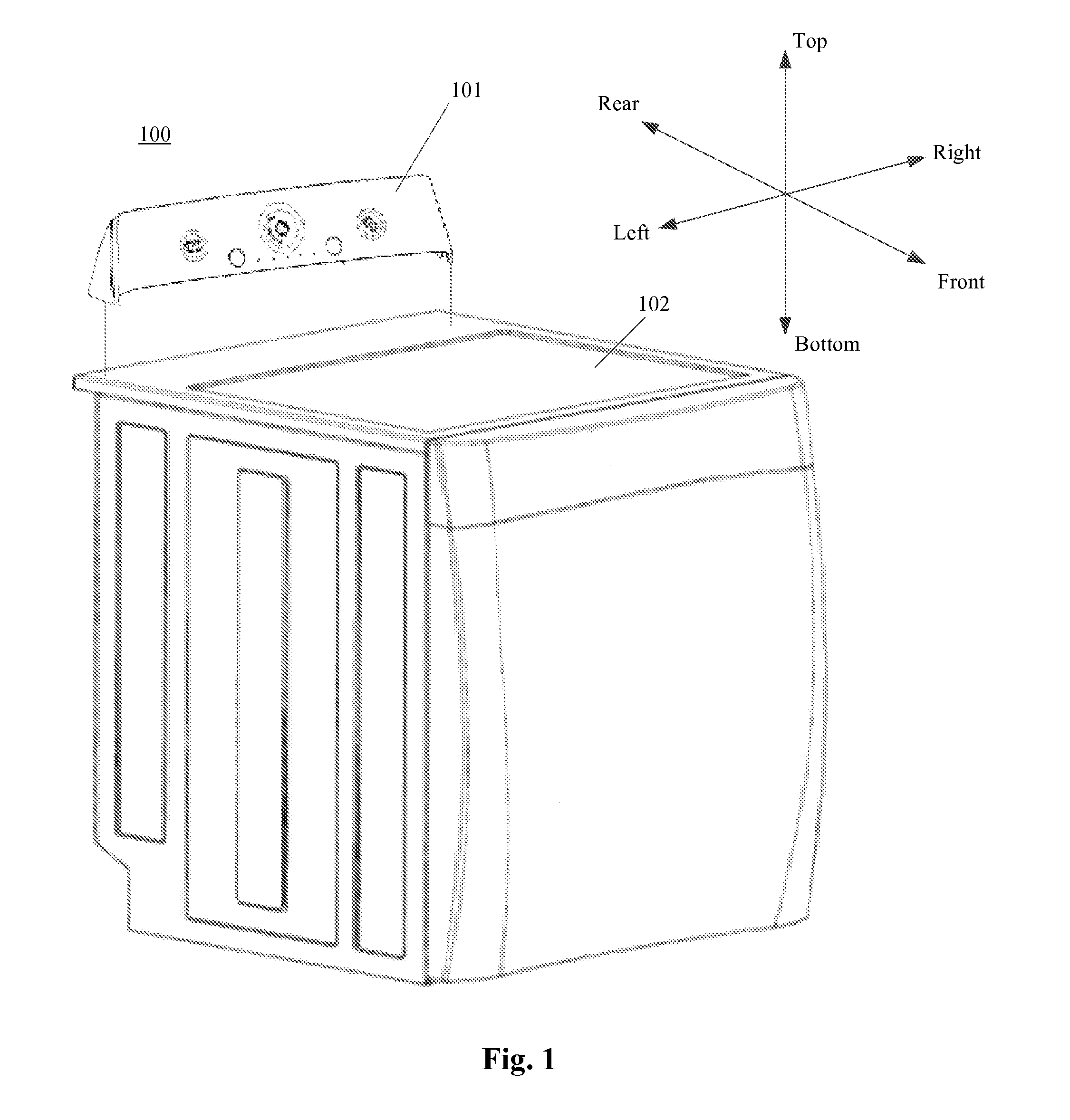
[0025]Referring to FIG. 1, a laundry machine 100 according to one aspect of the disclosure is depicted. The laundry machine 100 may include a control panel assembly 101 and a laundry machine cabinet 102. The control panel assembly 101 may connect to the outside surface of the laundry machine cabinet 102. In this example, the laundry machine 100 is depicted as a top loading washing machine, but the control panel assembly 101 may be connected to other laundry machines including front loading washers, dryers, or combination washer / dryer units. The control panel...


PUM


Abstract

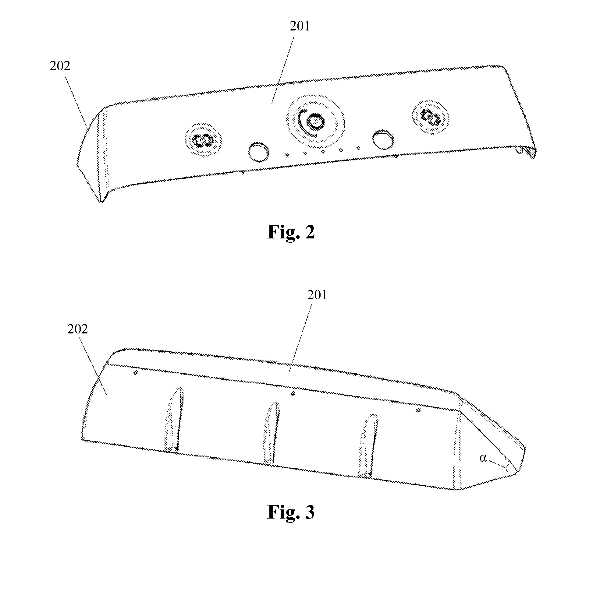
An appliance control panel assembly is provided comprising an upper fascia part and an angled lower base part. The control panel assembly may attach to the top surface of an appliance, such as a laundry machine, and may be removable. The upper fascia part may be configured to be slidably engaged to the angled lower base part and releasably connected to the angled lower base part by one or more flexible hooks and hook seats. The flexible hooks may be located on either the upper fascia part or the angled lower base part. The control panel assembly may also include disassembly holes through which an instrument can be inserted to deform the hooks and disconnect the upper fascia part from the angled lower base part.

Description

TECHNICAL FIELD[0001]The present disclosure relates generally to a control panel assembly for appliances, such as washing machines and dryers.BACKGROUND[0002]Many appliances such as laundry machines are controlled by a control panel located on an outside surface of the machine. Generally, the control panel displays information including machine status and washing / drying cycle options. The control panels of many laundry machines are permanently affixed to the outside surface of a cabinet during the manufacturing process, often through the use of hardware such as screws or bolts. Routine maintenance or diagnosing problems with the laundry machine may require removal of the control panel. The amount of time and expertise required to safely remove the control panel of many appliances may be problematic due to their permanent attachment.[0003]Even in appliances without permanently attached control panels, removing a control panel may be difficult. Wiring connecting the appliance to the i...

Claims


Application Information

Patent Timeline
IPC IPC(8): H05K7/00
CPCH05K7/00D06F34/28D06F2101/00D06F2105/58
Inventor BAS, ALBERTO
Owner ELECTROLUX APPLIANCES
Learn More