Pressure regulator of gas cylinder

a technology of pressure regulator and gas cylinder, which is applied in the direction of fluid pressure control, container discharge methods, instruments, etc., can solve the problems of increasing assembly difficulties, and affecting the operation of the pressure regulator

Active Publication Date: 2015-02-12
LI WEN HUNG +1
View PDF8 Cites 1 Cited by
  • Summary
  • Abstract
  • Description
  • Claims
  • Application Information

AI Technical Summary

Benefits of technology

[0010]It is therefore one object of the invention to provide a gas cylinder comprising a container body for storing pressurized contents; and a pressure regulator comprising a valve body releasably secured to the container body, the valve body including an upper first chamber, an intermediate second chamber, an intermediate third chamber, a lower channel communicating with interior of the container body, an internal passageway having one end communicating with the interior of the container body and a second end open on a first surface of the valve body, a lower through hole being through a lower portion of the valve body and communicating with both the intermediate third chamber and the lower channel, a port on a second surface of the valve body communicating with the first chamber, and an internally threaded top neck wherein the upper first chamber communicates with the intermediate second chamber which communicates with the intermediate third chamber; and the intermediate third chamber communicates with the lower channel; a high-pressure safety valve disposed at the second end of the passageway and configured to release pressure if pressure in the container body exceeds a first predetermined pressure level; a low-pressure safety valve disposed at one end of the lower through hole and communicating with both the intermediate third chamber and the lower channel, the low-pressure safety valve being configured to release pressure if pressure leaving the lower channel exceeds a second predetermined pressure level; a coupler connected to the port; a cylinder pressure gauge mounted at a second end of the lower through hole; an outlet pressure gauge mounted on the valve body above the cylinder pressure gauge; a moveable member disposed on a bottom of the intermediate third chamber; a spring biased hollow member disposed in the intermediate second chamber and having a bottom engaged a top of the moveable member; an externally threaded stem disposed in the upper first chamber and complimentarily disposed on the spring biased hollow member, the externally threaded stem including a transverse hole and a longitudinal hole having a top end communicating with the transverse hole and a bottom end communicating with interior of the spring biased hollow member; an internally threaded hollow cap threadedly secured onto the externally threaded stem which has an upper portion passes through the internally threaded hollow cap, the internally threaded hollow cap including external threads threadedly secured to the internally threaded top neck; and a knob mounted on the externally threaded stem; wherein in an inoperative state, the moveable member blocks the lower channel; and wherein the knob is configured to rotate to lift the externally threaded stem relative to the internally threaded hollow cap so that both the spring biased hollow member moves upward and the moveable member moves upward to unblock the lower channel, thereby forming a flow path from the container body, the lower channel, the intermediate third chamber, the intermediate second chamber, and the upper first chamber to the coupler.

Problems solved by technology

However, a number of drawbacks are found in the conventional gas cylinder.
The pressurized contents can damage the components.
Further, the components are complicated, thereby increasing difficulties of assembly.
Furthermore, maintenance cost can increase greatly.

Method used


Image

  • Pressure regulator of gas cylinder
  • Pressure regulator of gas cylinder
  • Pressure regulator of gas cylinder

Examples


Embodiment Construction

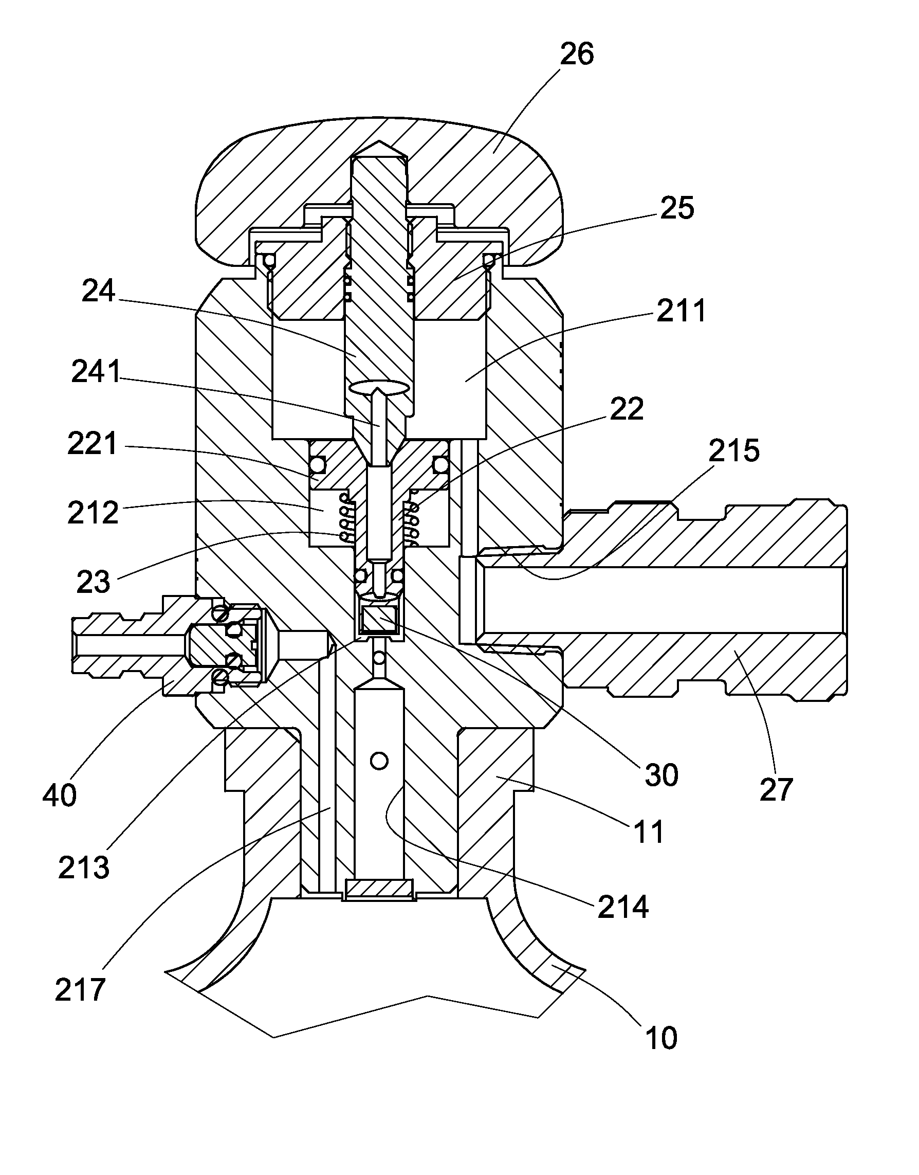
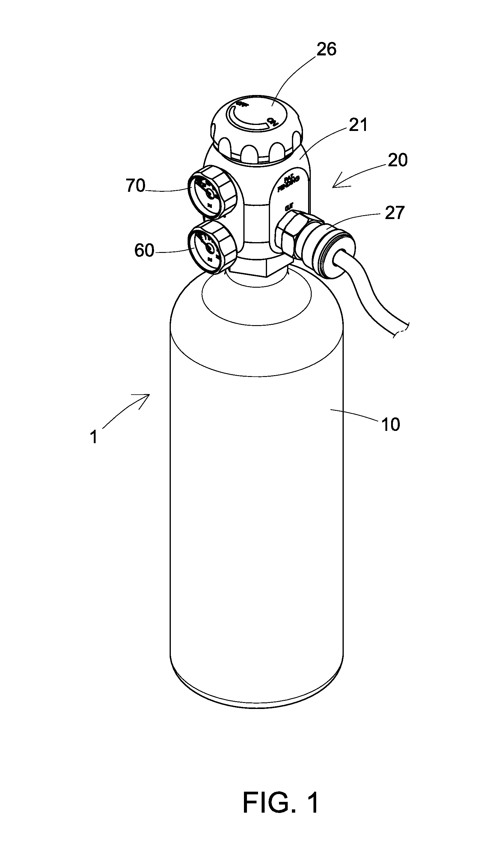
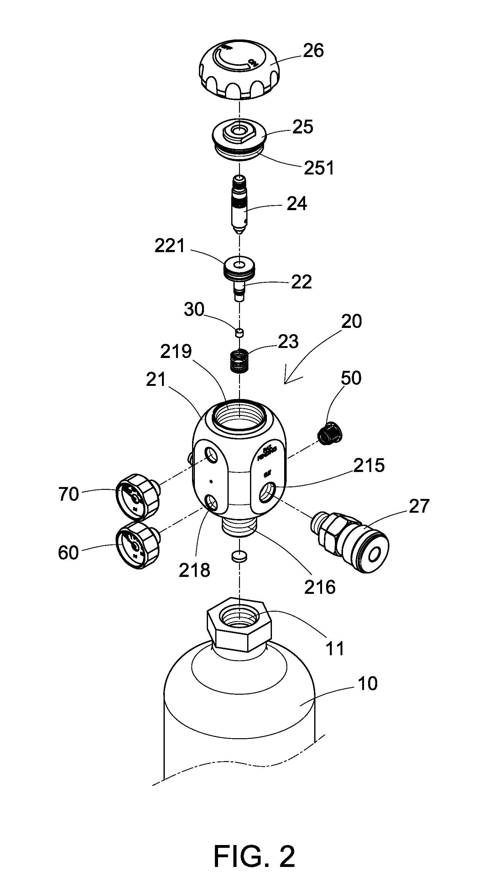
[0018]Referring to FIGS. 1 to 4, a gas cylinder 1 in accordance with the invention comprises the following components as discussed in detail below.

[0019]Gases having pressure above atmospheric pressure (i.e., pressurized contents) are stored in a container body 10. An internally threaded opening 11 is provided on a top of the container body 10. A pressure regulator 20 comprises a valve body 21 including a hollow, externally threaded extension 216 at a bottom being threadedly fastened in the internally threaded opening 11 to secure the container body 10 and the valve body 21 (i.e., the pressure regulator 20) together, an upper first chamber 211, an intermediate second chamber 212, an intermediate third chamber 213, a lower channel 214 through the hollow, externally threaded extension 216, an internal passageway 217 having one end communicating with interior of the container body 10 and a second end open on a second surface of the valve body 21, a lower through hole 218 under the uppe...


PUM


Abstract

A gas cylinder is provided with a pressure regulator including a valve body including an upper first chamber, intermediate second and third chambers, a lower channel threadedly secured to and communicating with a container body, a passageway having one end communicating with the container body, a lower through hole communicating with the intermediate third chamber and the channel, and an internally threaded top neck; a high-pressure safety valve; a low-pressure safety valve; a coupler on the valve body; a moveable member on a bottom of the intermediate third chamber; a spring biased hollow member in the intermediate second chamber and having a bottom engaged the moveable member; an externally threaded stem in the upper first chamber and complimentarily disposed on the hollow member; a hollow cap threadedly secured to the stem and the neck respectively; and a knob mounted on the stem.

Description

BACKGROUND OF THE INVENTION[0001]1. Field of the Invention[0002]The invention relates to pressure vessels and more particularly to a pressure regulator of a gas cylinder with improved characteristics.[0003]2. Description of Related Art[0004]A conventional gas cylinder is shown in FIGS. 5 and 6 and includes a pressure regulator 90 mounted on a container body 80. The pressure regulator 90 includes a valve body 91 having an upper chamber 911, an intermediate chamber 912, a lower channel 913 communicating with the interior of the container body 80, and a port 914 communicating with the upper chamber 911. The upper chamber 911 communicates with the intermediate chamber 912 which communicates with the lower channel 913.[0005]The pressure regulator 90 further includes a hollow member 92 including an enlarged head 921, the hollow member 92 provided in the intermediate 912 and having a bottom engaged a top opening the lower channel 913; a compression spring 93 put on the shank of the hollow ...

Claims


Application Information

Patent Timeline
Patent Type & Authority Applications(United States)
IPC IPC(8): F16K17/168F16K31/60F17C13/04F16K37/00F17C13/00
CPCF16K17/168F16K37/0066F17C13/002F17C2205/0329F16K31/60F17C2205/0338F17C2205/0332F17C13/04F16K1/305F17C2201/0109F17C2201/056F17C2201/058F17C2205/0385F17C2205/0394F17C2223/0123F17C2223/036G05D16/103Y10T137/8326
Inventor LI, WEN-HUNGHUANG, CHUNG WEI
Owner LI WEN HUNG
Why Eureka
Try Eureka