
Channel Monitoring With Plural Frequency Agile Receivers

a receiver and channel monitoring technology, applied in the field of scanning radio receivers, can solve the problems of inability to detect insensitive to any radio communications on other channels, and inability to meet the needs of radio receivers, etc., to achieve the effect of improving the signal detection and capture efficiency of a group of radio receivers

Active Publication Date: 2014-11-06
TELEGRAPH PEAK TECH LLC
View PDF9 Cites 7 Cited by
  • Summary
  • Abstract
  • Description
  • Claims
  • Application Information

AI Technical Summary

Benefits of technology

This approach improves signal detection and capture efficiency, enabling comprehensive monitoring of multiple channels exceeding the number of receivers, reducing missed transmissions and enhancing continuous reception across a larger number of channels.

Problems solved by technology

However, heavy radio use demand and congested airways caused manufacturers to develop more spectrally efficient radio systems.
Since any individual channel will typically have long periods of inactivity, this technology is a practical way to monitor communications on multiple channels with a single receiver, although it is typically not plausible to receive simultaneous communications on different channels with a single receiver.
When a single receiver is receiving a transmission on one channel, it is typically insensitive to any radio communications on other channels.
In general, continuity of reception is desirable, and missed transmissions represent a deficiency in the system performance.
However, for large numbers of channels, operating an equal number of receivers can become prohibitively expensive in terms of both electrical equipment and physical housing requirements.
However, a technique built upon permanently dedicated receivers becomes impractical due to the proliferation of separate frequencies to monitor when the channels to monitor include channels not carried by a particular trunked radio system.
However this method has serious shortcomings that limit its practical utility for comprehensive detection and reception of active signals on multiple channels.
During a period when multiple receivers are monitoring the same signal, the intended benefit of using multiple receivers for more complete reception coverage is lost.
This renders ineffective the option of programming a group of scanners identically, with the scan list of all desired channels.
It is an intrinsic disadvantage of priority mode operation that an ongoing reception must me periodically interrupted to check the priority channel.
However, whenever the number of monitored channels is greater than the number of available radio receivers, as is typically the case when scanners are used, since otherwise it would be possible to have a single dedicated receiver for each channel, this approach becomes ineffective for ensuring effective coverage of the entire set of channels even if the number of active channels is typically smaller than the number of available radio receivers.
Avoiding any channel duplication in the multiple receivers eliminates the problem of multiple receivers locking on the same signal, which would clearly reduce the effectiveness of having multiple receivers.
However, if there is simultaneous activity on two of the channels in the scan list of a any individual receiver, then one of these signals will be missed, even if one or more of the other receivers are scanning and not presently monitoring any active signals.
The phenomenon of missed transmissions presents a problem for any users who wish to comprehensively monitor traffic on a significant number of channels.
The ability of users to perform these functions is severely hampered by the lack of a technology in the prior art for effectively utilizing a group of multiple radio receivers to dynamically receive up to the same number of simultaneous signals, regardless of the particular set of channels active at that time.

Method used


Image

  • Channel Monitoring With Plural Frequency Agile Receivers
  • Channel Monitoring With Plural Frequency Agile Receivers
  • Channel Monitoring With Plural Frequency Agile Receivers

Examples


Embodiment Construction

[0065]Illustrative embodiments and exemplary applications will now be described with reference to the accompanying drawings to disclose the advantageous teachings of the present invention.

[0066]While the present invention is described herein with reference to illustrative embodiments for particular applications, it should be understood that the invention is not limited thereto. Those having ordinary skill in the art and access to the teachings provided herein will recognize additional modifications, applications, and embodiments within the scope hereof and additional fields in which the present invention would be of significant utility.

[0067]In considering the detailed embodiments of the present invention, it will be observed that the present invention resides primarily in combinations of steps to accomplish various methods or components to form various apparatus and systems. Accordingly, the apparatus and system components and method steps have been represented where appropriate by...


PUM


Abstract

A system and method to efficiently use a plurality of ‘receivers’ to monitor a larger plurality of ‘sources’ for audio content. Upon identifying that a source is active, one of the plural receivers is assigned to convey the content to a destination. All other receivers are prevented from monitoring that specific source for the duration of its activity, but continue to monitor the remaining sources. ‘Source’ includes any source of information containing audio content. ‘Receiver’ includes any device capable of selectively conveying such content, including physical switches, hardware or software multiplexers, microphones, radio receivers, or any other means of obtaining such content.

Description

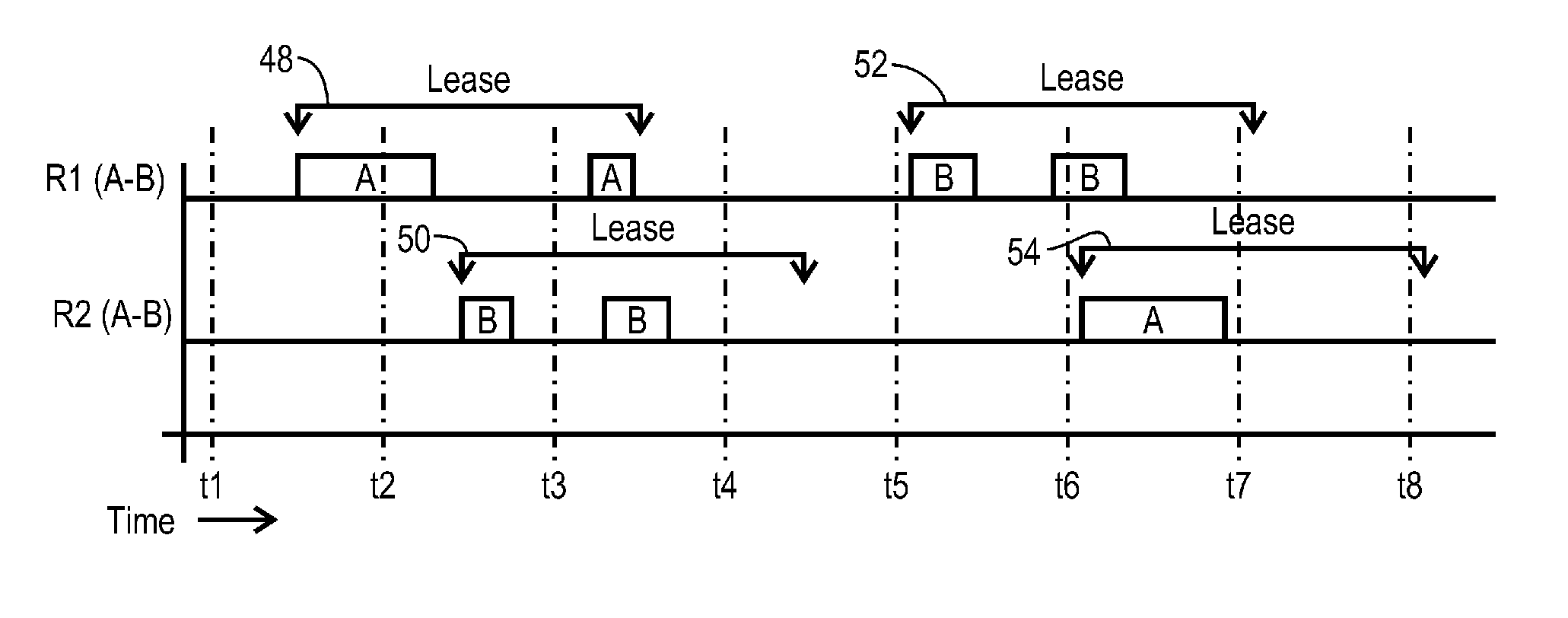
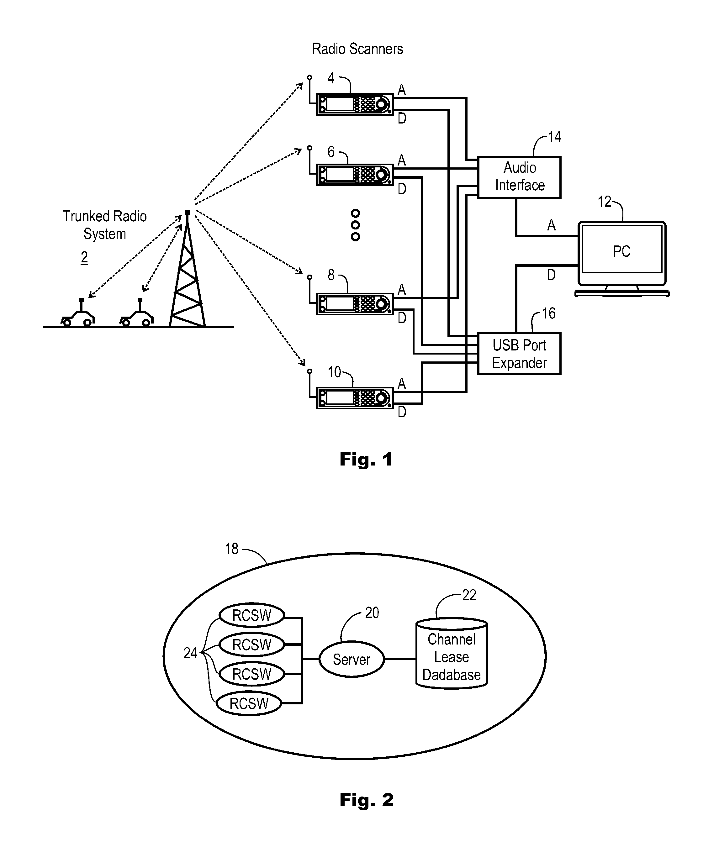
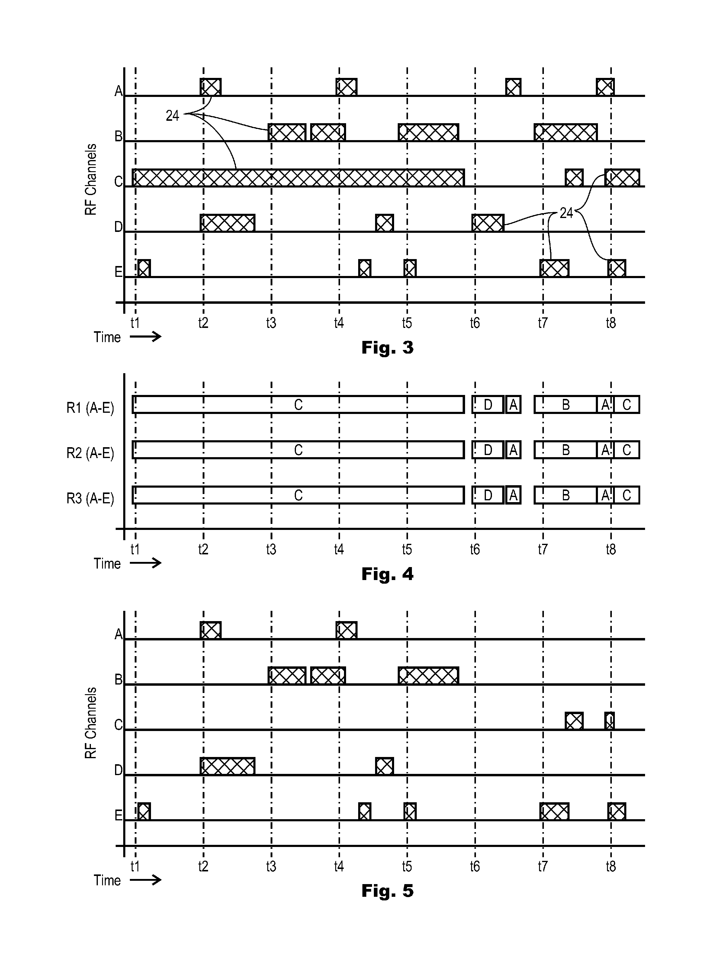
BACKGROUND OF THE INVENTION[0001]1. Field of the Invention[0002]The present invention relates to scanning radio receivers. More particularly, the present invention relates to control systems for optimizing the efficiency of reception of intermittent audio content broadcast on plural channels and received by plural frequency agile receivers.[0003]2. Description of the Related Art[0004]Scanning radio receivers, commonly known as “police scanners” or simply “scanners”, allow users to listen to police, fire, aircraft, marine, business and other manner of one-way and two-way radio communications across a broad spectrum of frequencies, typically from 25 MHz to 1300 MHz, and including higher frequencies as well. Scanners typically have a channel memory that is used to store one or more receiver frequencies, or indicia of frequency, which can be recalled by referencing a channel number, thereby simplifying the entry and selection of desired reception frequencies. Various types of scanners a...

Claims


Application Information

Patent Timeline
Patent Type & Authority Applications(United States)
IPC IPC(8): H04B1/16H04W84/08
CPCH04W84/08H04B1/16H04W48/16H04B1/18H03J7/18
Inventor SULLIVAN, TERENCE SEAN
Owner TELEGRAPH PEAK TECH LLC
Learn More