
Method for encoding and decoding images based on constrained offset compensation and loop filter, and apparatus therefor

a technology of offset compensation and loop filter, applied in the field of digital video, can solve the problems of inability to decode compressed video bit streams, easy errors, and degrade the image quality of reconstructed videos

Active Publication Date: 2014-09-25
ELECTRONICS & TELECOMM RES INST
View PDF6 Cites 17 Cited by
  • Summary
  • Abstract
  • Description
  • Claims
  • Application Information

AI Technical Summary

Benefits of technology

The patent allows for better handling of videos by applying an offset compensation or loop filter that helps overcome errors during encoding and decoding. This results in improved quality of the video.

Problems solved by technology

The technical problem addressed in this patent text relates to improving the resilience of offset compensation and loop filters used during video compression to mitigate errors introduced while transmission over networks.

Method used


Image

  • Method for encoding and decoding images based on constrained offset compensation and loop filter, and apparatus therefor
  • Method for encoding and decoding images based on constrained offset compensation and loop filter, and apparatus therefor
  • Method for encoding and decoding images based on constrained offset compensation and loop filter, and apparatus therefor

Examples


Embodiment Construction

[0024]Hereinafter, exemplary embodiments of the present invention will be described in detail with reference to the accompanying drawings. Further, in describing exemplary embodiments of the present invention, well-known functions or constructions will not be described in detail since they may unnecessarily obscure the understanding of the present invention.

[0025]It is to be understood that when any element is referred to as being “connected to” or“coupled to” another element, it may be connected directly to or coupled directly to another element or be connected to or coupled to another element, having the other element intervening therebetween. Further, in the present specification, in the case of describing “including” a specific component, it is to be understood that additional components other than a corresponding component are not excluded, but may be included in exemplary embodiments or the technical scope of the present invention.

[0026]Terms used in the specification, ‘first’...


PUM


Abstract

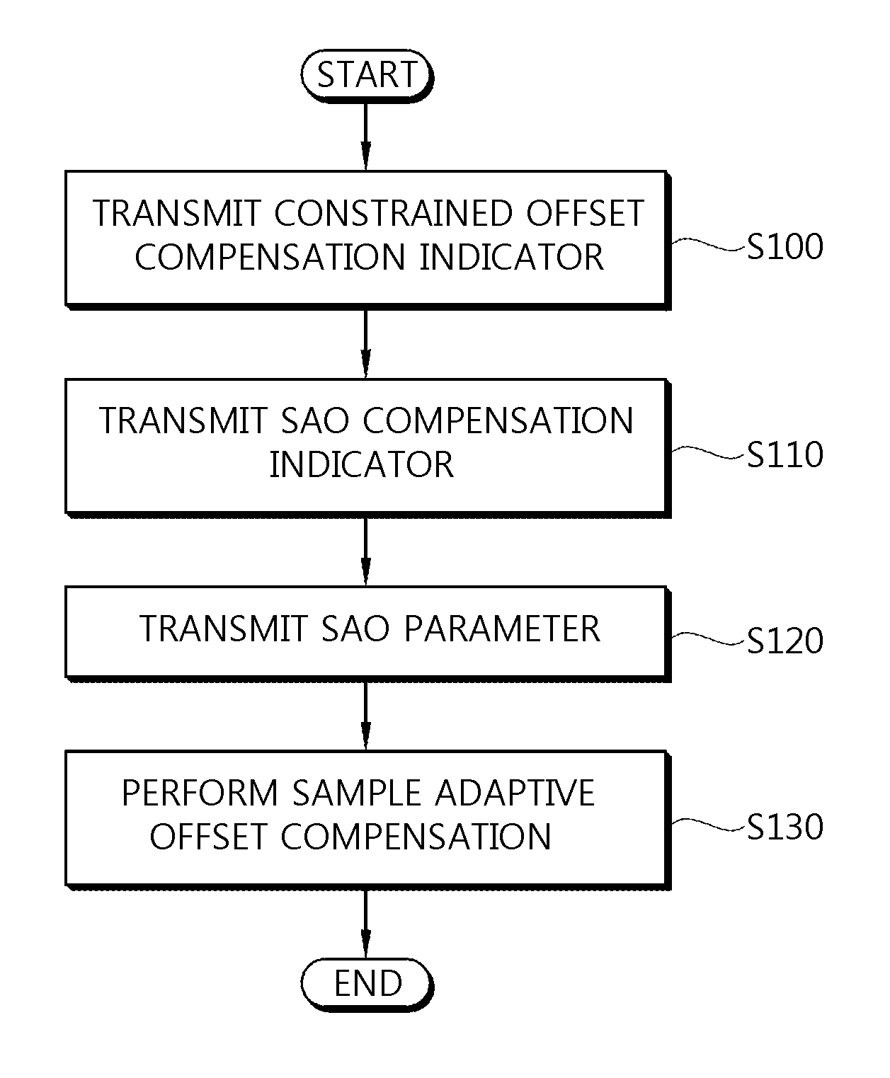
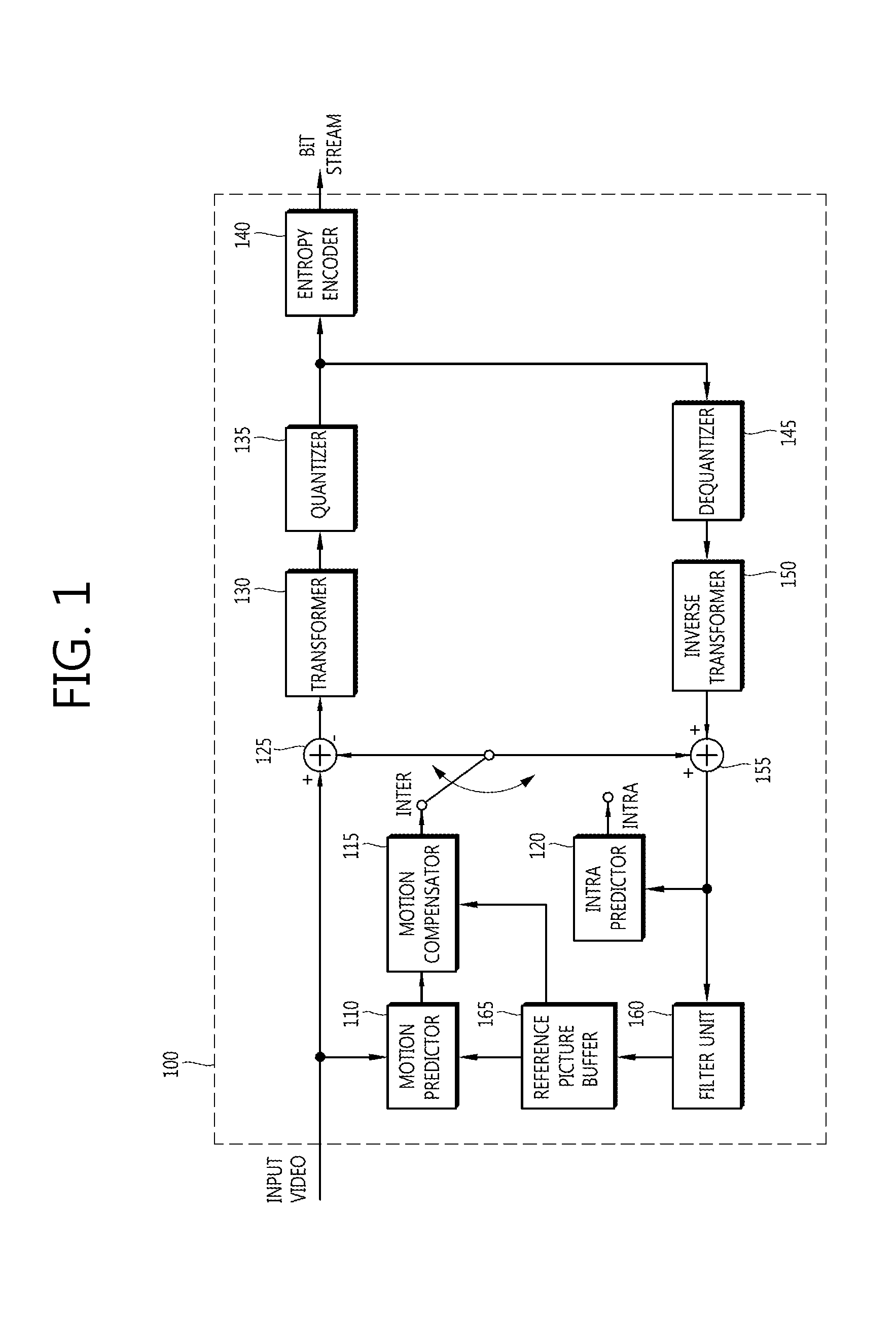
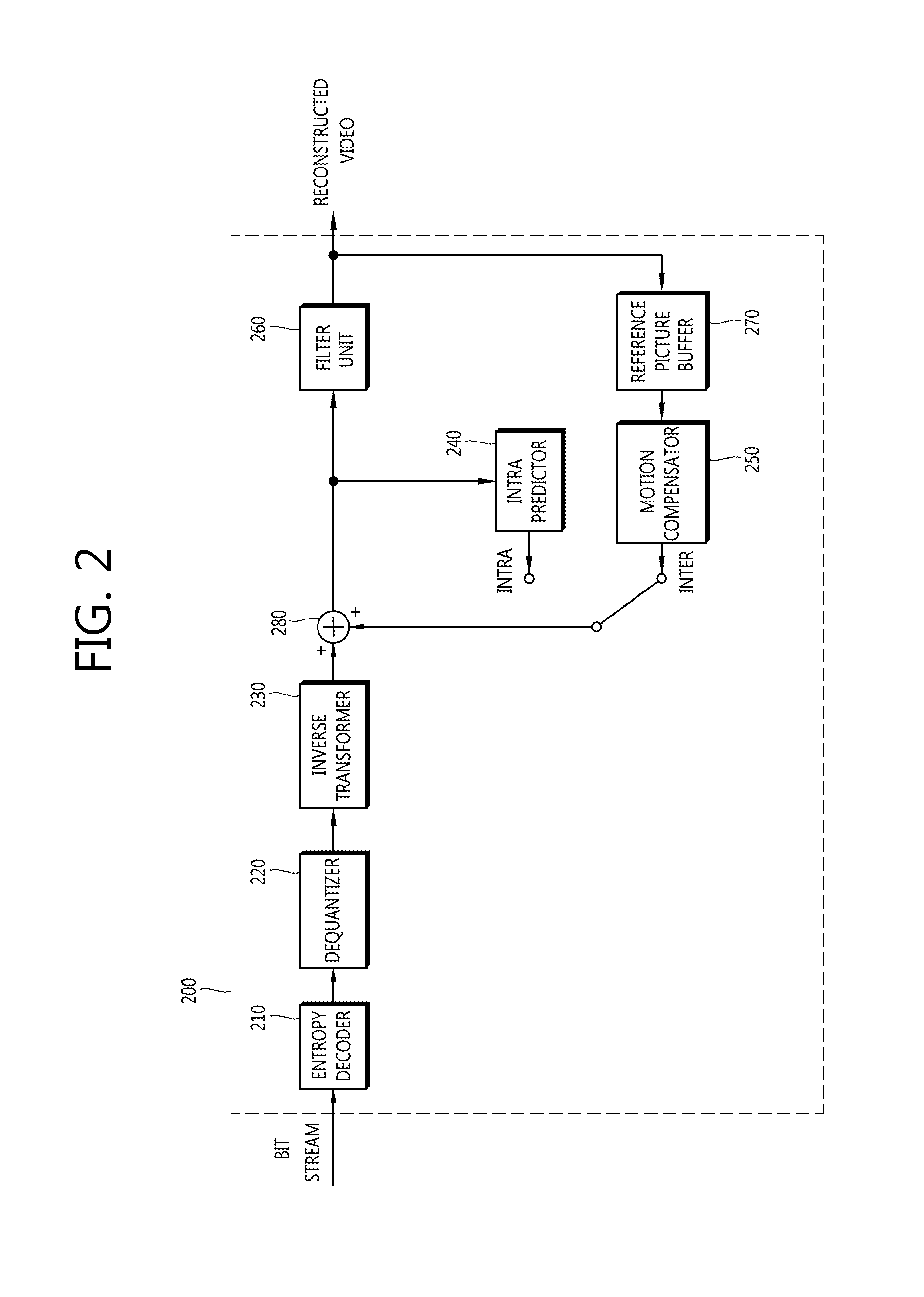
Provided are a method and apparatus for encoding and decoding images based on constrained offset compensation and a loop filter. The image decoding apparatus: receives, from an encoder, a first indicator indicating whether a sequence, a picture, a frame, a slice, a coding unit (CU), a prediction unit (PU), and/or a transform unit (TU) supports constrained offset compensation; receives, from the encoder, a second indicator indicating whether constrained sample adaptive offset (SAO) compensation or an adaptive loop filter (ALF) is applied; receives a parameter from the encoder; and applies the SAO compensation or the ALF to pixels of a restored image on the basis of the second indicator and the parameter.

Description


Claims


Application Information

Patent Timeline
Owner ELECTRONICS & TELECOMM RES INST
Learn More