Surgical stapling instrument

a surgical severing and instrument technology, applied in the field of surgical instruments, can solve the problems of complicated approaches to articulating a surgical severing and severing instrumen

Inactive Publication Date: 2014-06-05
CILAG GMBH INT +1
View PDF6 Cites 1358 Cited by
  • Summary
  • Abstract
  • Description
  • Claims
  • Application Information

AI Technical Summary

Benefits of technology

The present invention relates to a surgical instrument that is suitable for endoscopically inserting an end effector that is actuated by a longitudinally driven firing member. More specifically, the invention is about a surgical stapling and severing instrument that has an articulating shaft, which allows the end effector to be positioned at an axis transverse to the instrument shaft. This articulation feature allows for better surgical placement of staple lines and easier tissue manipulation and orientation. The invention also includes improvements made through the use of an E-beam firing bar that allows for several beneficial lockouts and the incorporation of a pivot joint in the extended shaft. Overall, the invention provides a surgical instrument that is more versatile and better suited for endoscopic surgery.

Problems solved by technology

Approaches to articulating a surgical stapling and severing instrument tend to be complicated by integrating control of the articulation along with the control of closing the end effector to clamp tissue and fire the end effector (i.e., stapling and severing) within the small diameter constraints of an endoscopic instrument.

Method used


Image

  • Surgical stapling instrument
  • Surgical stapling instrument
  • Surgical stapling instrument

Examples


Embodiment Construction

[0031]The entire disclosure of U.S. patent application Ser. No. 11 / 082,495, entitled SURGICAL INSTRUMENT INCORPORATING AN ELECTRICALLY ACTUATED ARTICULATION MECHANISM, filed on Mar. 17, 2005, now U.S. Pat. No. 7,506,790, is incorporated herein by reference. The entire disclosure of U.S. Pat. No. 6,667,825, entitled STABLE CONJUGATED POLYMER ELECTROCHROMIC DEVICES INCORPORATING IONIC LIQUIDS, issued on Jan. 3, 2002, is incorporated herein by reference. The entire disclosure of U.S. patent application Ser. No. 11 / 061,908, entitled SURGICAL INSTRUMENT INCORPORATING A FLUID TRANSFER CONTROLLED ARTICULATION MECHANISM, filed on Feb. 18, 2005, now U.S. Pat. No. 7,559,450, is incorporated herein by reference.

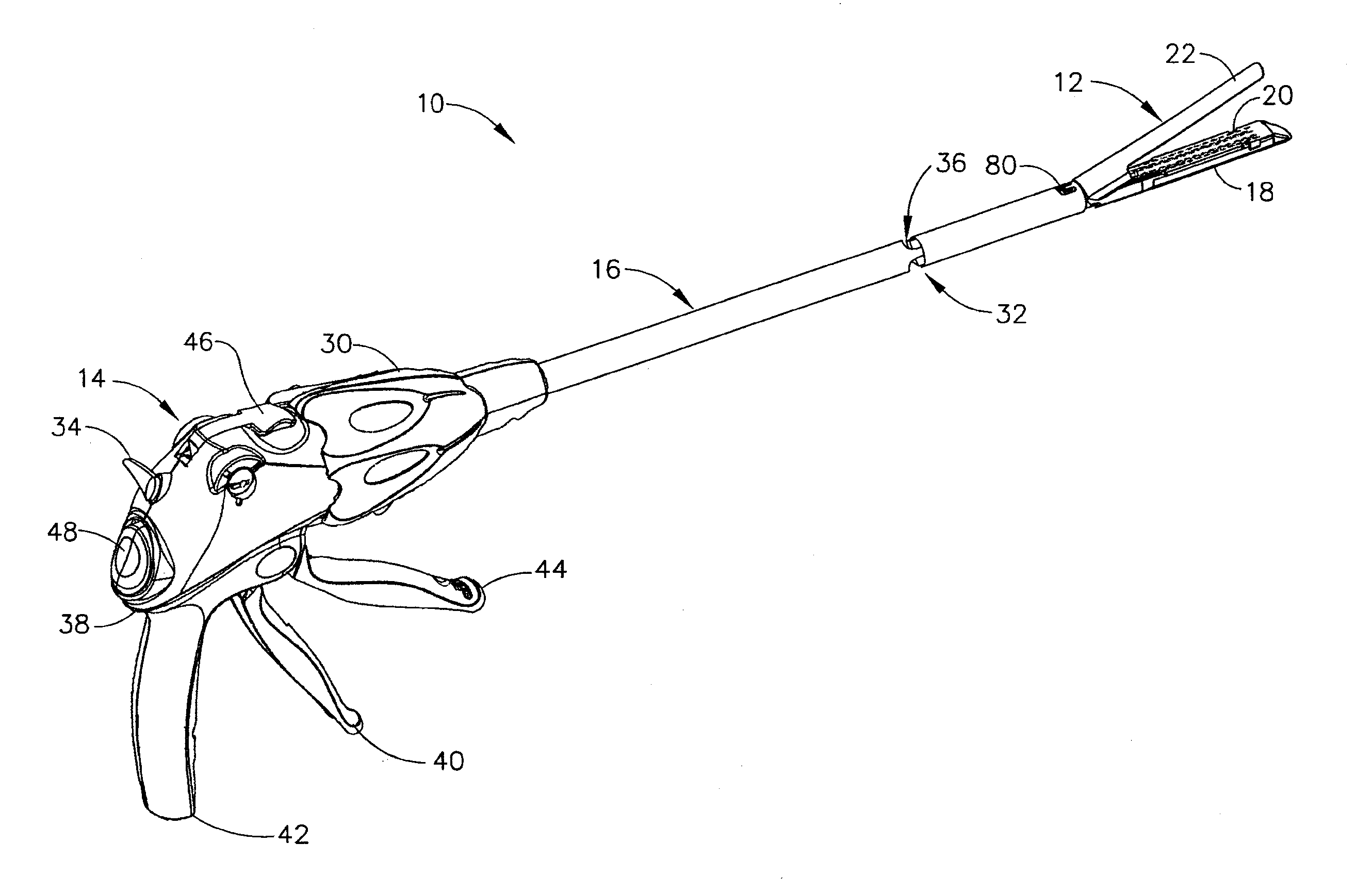
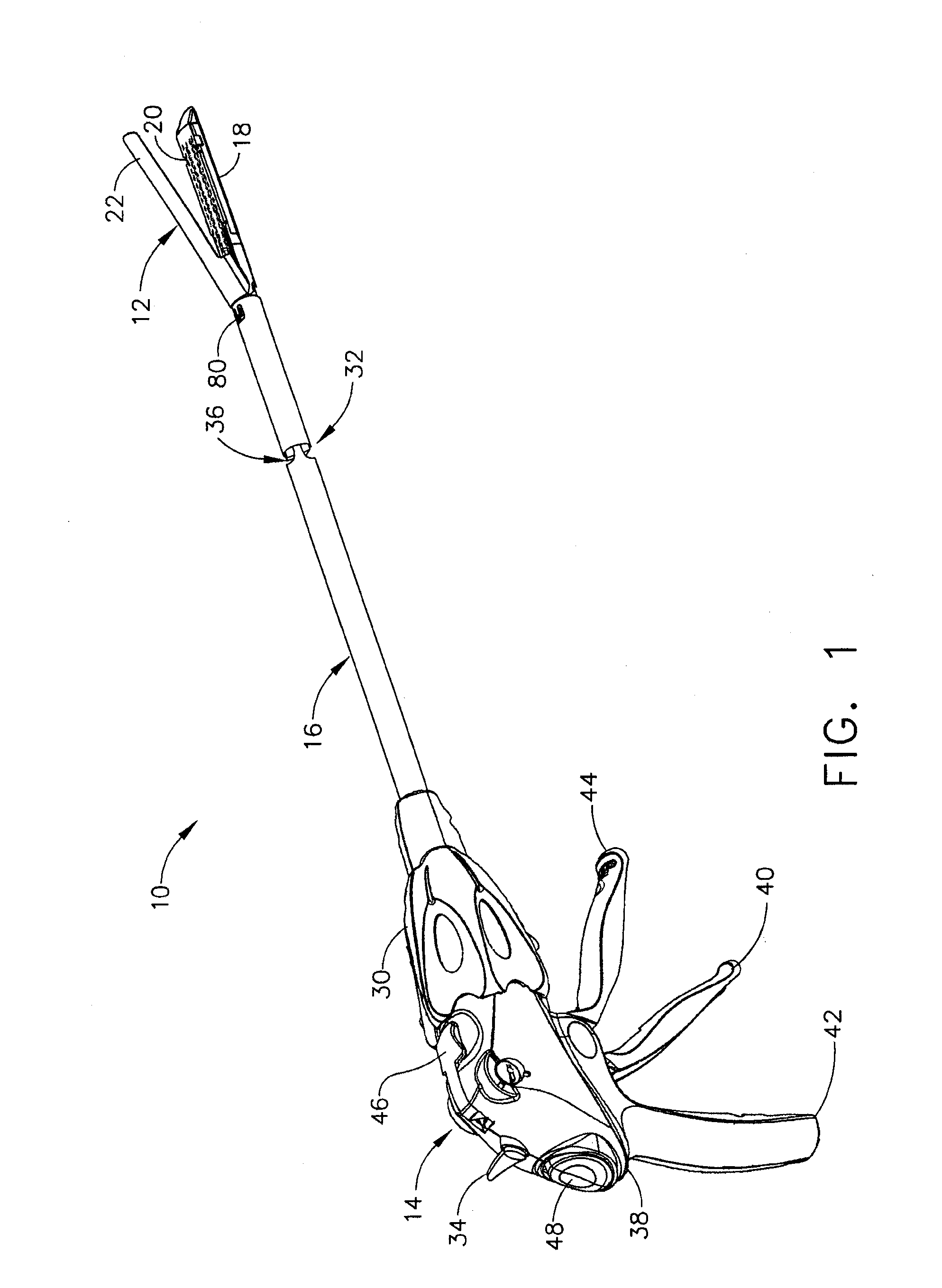
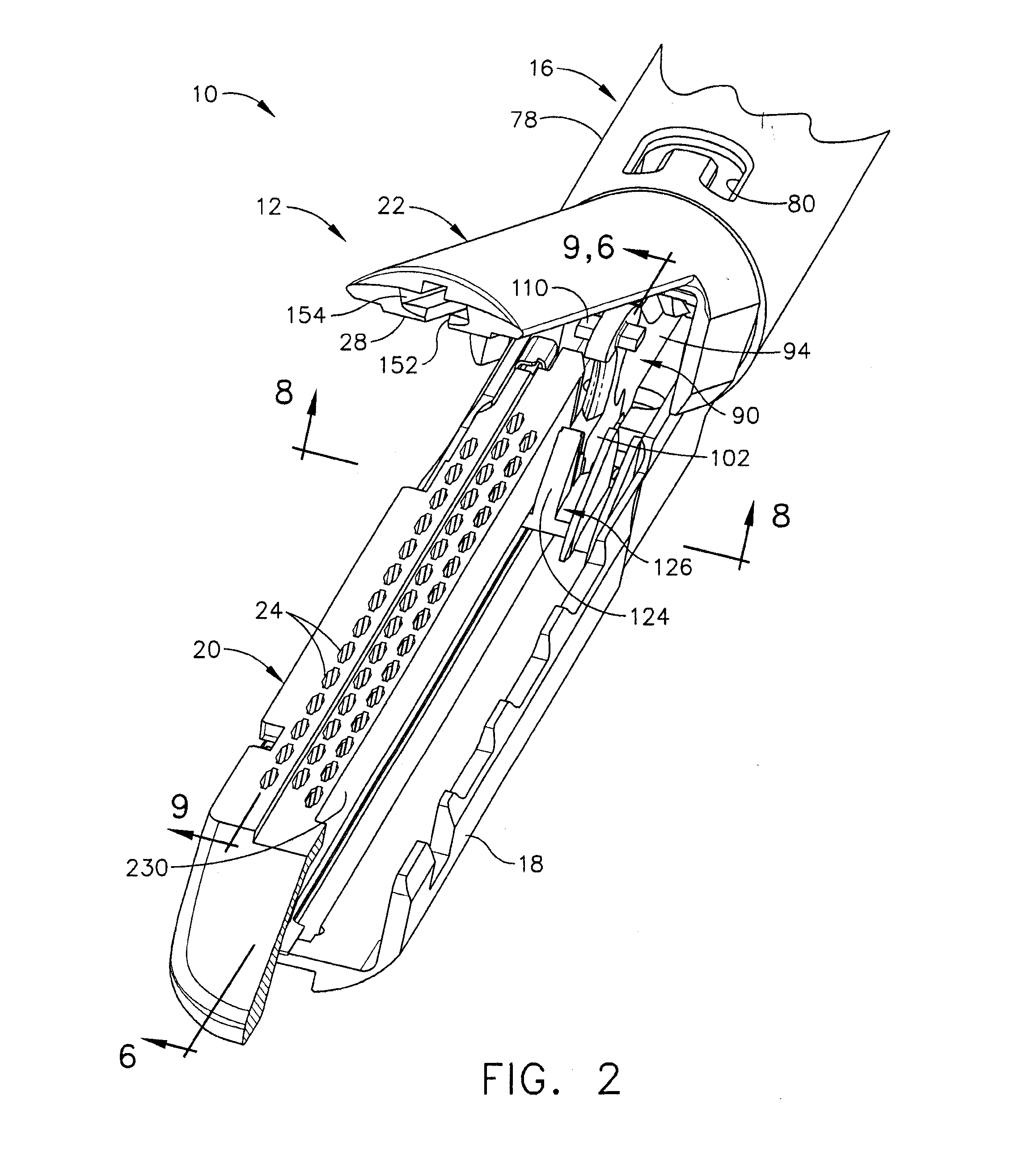
[0032]In FIGS. 1-3, a surgical stapling instrument 10 has at its distal end an end effector, depicted as a staple applying assembly 12, spaced apart from a handle 14 (FIG. 2) by an elongate shaft 16. The staple applying assembly 12 includes a staple channel 18 for receiving a replaceabl...


PUM


Abstract

A surgical severing and stapling instrument, suitable for laparoscopic and endoscopic clinical procedures, clamps tissue within an end effector of an elongate channel pivotally opposed by an anvil. An E-beam firing bar moves distally through the clamped end effector to sever tissue and to drive staples on each side of the cut. The E-beam firing bar affirmatively spaces the anvil from the elongate channel to assure properly formed closed staples, especially when an amount of tissue is clamped that is inadequate to space the end effector. In particular, an upper pin of the firing bar longitudinally moves through an anvil slot and a channel slot is captured between a lower cap and a middle pin of the firing bar to assure a minimum spacing. Forming the E-beam from a thickened distal portion and a thinned proximal strip enhances manufacturability and facilitates use in such articulating surgical instruments.

Description

CROSS-REFERENCE TO RELATED APPLICATIONS[0001]The present application is a continuation application under 35 U.S.C. §120 of U.S. patent application Ser. No. 13 / 369,601, entitled ROBOTICALLY-CONTROLLED SURGICAL END EFFECTOR SYSTEM, filed on Feb. 9, 2012, now U.S. Patent Application Publication No. 2012 / 0203247, which is a continuation application under 35 U.S.C. §120 of U.S. patent application Ser. No. 13 / 118,246, entitled ROBOTICALLY-DRIVEN SURGICAL INSTRUMENT WITH E-BEAM DRIVER, filed on May 27, 2011, now U.S. Patent Application Publication No. 2011 / 0290853, which is a continuation-in-part application under 35 U.S.C. §120 of U.S. patent application Ser. No. 11 / 538,154, entitled ARTICULATING SURGICAL STAPLING INSTRUMENT INCORPORATING A TWO-PIECE FIRING MECHANISM, filed on Oct. 3, 2006, the entire disclosures of which are incorporated by reference herein. The present application is a continuation application under 35 U.S.C. §120 of U.S. patent application Ser. No. 11 / 141,753, entitled...

Claims


Application Information

Patent Timeline
Patent Type & Authority Applications(United States)
IPC IPC(8): A61B17/068A61B17/072
CPCA61B17/0682A61B17/072A61B17/07207A61B17/320092A61B34/30A61B34/37A61B50/20A61B50/36A61B2017/00017A61B2017/00398A61B2017/00473A61B2017/00734A61B2017/0688A61B2017/07271A61B2017/07278A61B2017/2923A61B2017/2927A61B2017/320052A61B18/1445A61B2017/07285A61B2018/00607A61B2018/0063A61B2018/1455A61B2090/0807A61B2017/320093A61B17/04A61B17/115A61B17/122A61B2034/302A61B2017/320094A61B2017/320095A61B2017/320097A61B17/064A61B17/068A61B17/105A61B2017/07257
Inventor SHELTON, IV, FREDERICK E.SETSER, MICHAEL E.WEISENBURGH, II, WILLIAM B.
Owner CILAG GMBH INT
Why Eureka
Try Eureka