Eye examination apparatus with digital image output

a digital image and eye examination technology, applied in the field of eye examination equipment, can solve the problems of inexpedient positioning inconvenient coordination for the examining person, and inability to observe via a screen during the examination

Active Publication Date: 2013-10-31
HAAG STREIT AG
View PDF3 Cites 7 Cited by
  • Summary
  • Abstract
  • Description
  • Claims
  • Application Information

AI Technical Summary

Benefits of technology

[0005]It is an object of the invention to develop a device for stereoscopically examining an eye, which is part of the technical field mentioned at the outset and which is more ergonomic and enables improved operation.
[0010]The image sensor can be designed to be sufficiently large for it to be possible, thereon, to record the two images next to one another at the same time. The image sensor can also record the two half-images alternately in time, particularly if the sensor can process individual images with a sufficiently high frequency, e.g. greater than or equal to 100 Hz. However, a disadvantage may arise as a result of the fact that only half the image frequency can be obtained using the same image sensor. In the case of rapid eye movements of the observed eye, the image pairs may, as a result thereof, not be matched sufficiently well to one another or not have a sufficient degree of synchronicity for the purposes of stereoscopic observation, and so the quality of the 3D effect during the observation may be too low. However, depending on the recording frequency attained by the image sensor, this may nevertheless be accepted, particularly if this allows for a more compact design of the device. In a further preferred variant, provision is made for an interlace technique, in which the pixel sensors record the left and the right half-image, alternating line-by-line. To this end, the pixel lines can alternately be embodied in such a way that, for example by means of suitable lens elements, a light ray is only captured by a first pixel line if it has a specific angle of incidence α, while a second pixel line only captures a light ray if it has an angle of incidence β≠α, as a result of which it is possible to keep the two half-images apart.
[0015]The provision of the two eyepieces for stereoscopically observing the two images renders it possible that the device per se is available in a known form familiar to the user. Moreover, this form of the stereoscopic display of recorded image material constitutes a particularly simple variant, particularly because the observer does not need to re-accustom himself from conventional devices for stereoscopically observing an eye.
[0019]In a first variant, the observation unit can be fixed with respect to the eye to be observed, for example by means of a latching device, while the optical unit remains pivotable independently of the observation unit. As a result, the observer can observe the eye and change the observation angle with respect to the eye, without it being necessary to move the observation unit. As a result, a more ergonomic examination is made possible for the observer.
[0021]In a third variant, both the observation unit and the optical unit can be moved independently. This can be advantageous if there are two observers (e.g. trainer and trainee) and one wishes to pass the observation unit to the other. This is because there is no need to swap positions in this case. The optical unit can remain fixed while the observation unit is pivoted.
[0024]In some variants the observation unit can also be mounted in a fixed fashion relative to the optical unit. As a result thereof, the observer does not need to re-accustom himself from the conventional devices.

Problems solved by technology

A disadvantage of these devices is that the coordination is unfamiliar to the examining person when operating the device and at the same time observing the image material on the screen.
Furthermore, the observation via a screen during the examination is not optimal because the screen must have a certain distance from the observer so that the observer can easily and quickly focus on the screen.
In almost every case, the positioning is inexpedient for the examining person and the examined person, and for design reasons.

Method used


Image

  • Eye examination apparatus with digital image output
  • Eye examination apparatus with digital image output
  • Eye examination apparatus with digital image output

Examples


first embodiment

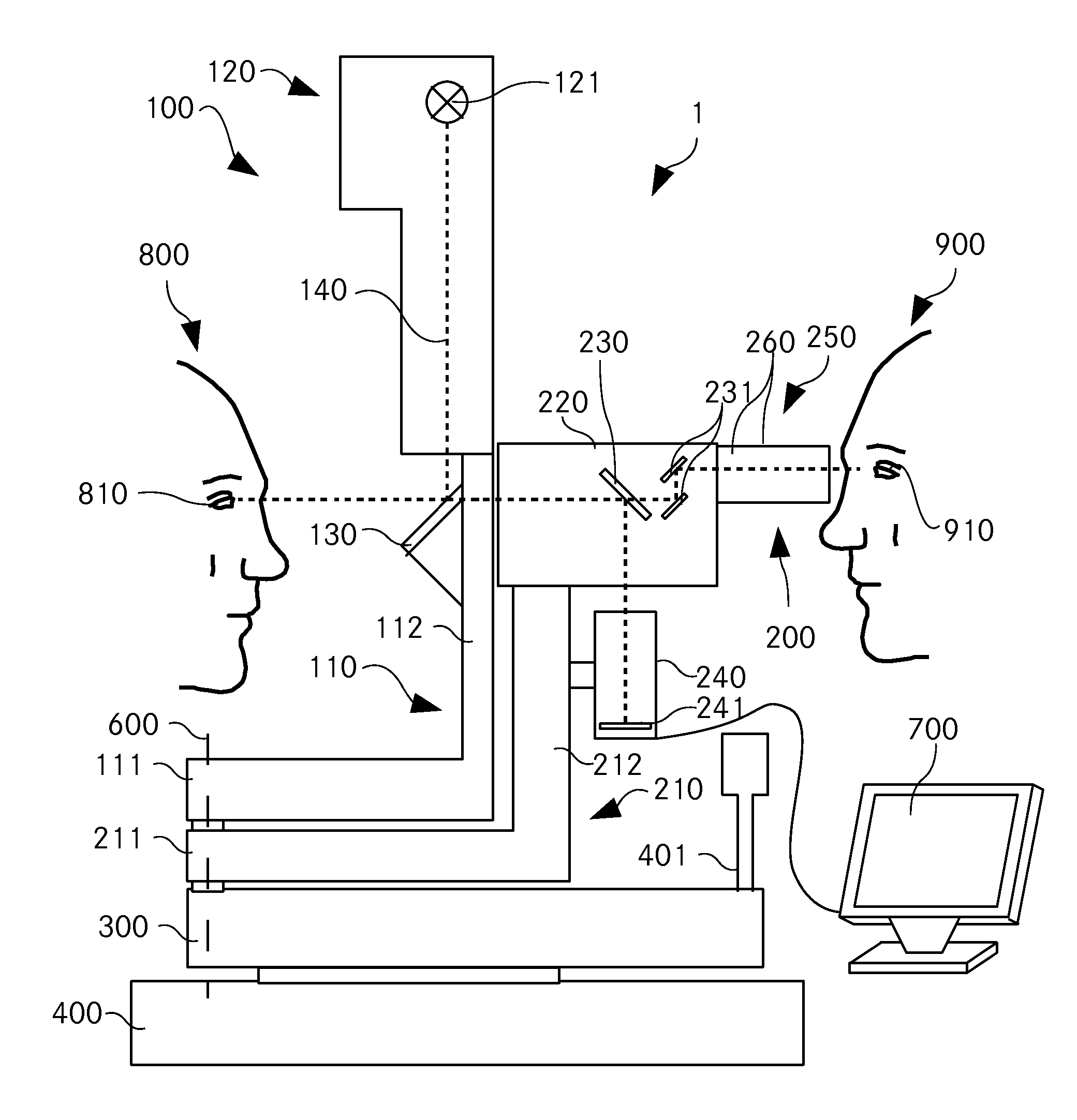
[0048]FIG. 1 shows a schematic illustration of a side view of a device for examining an eye;

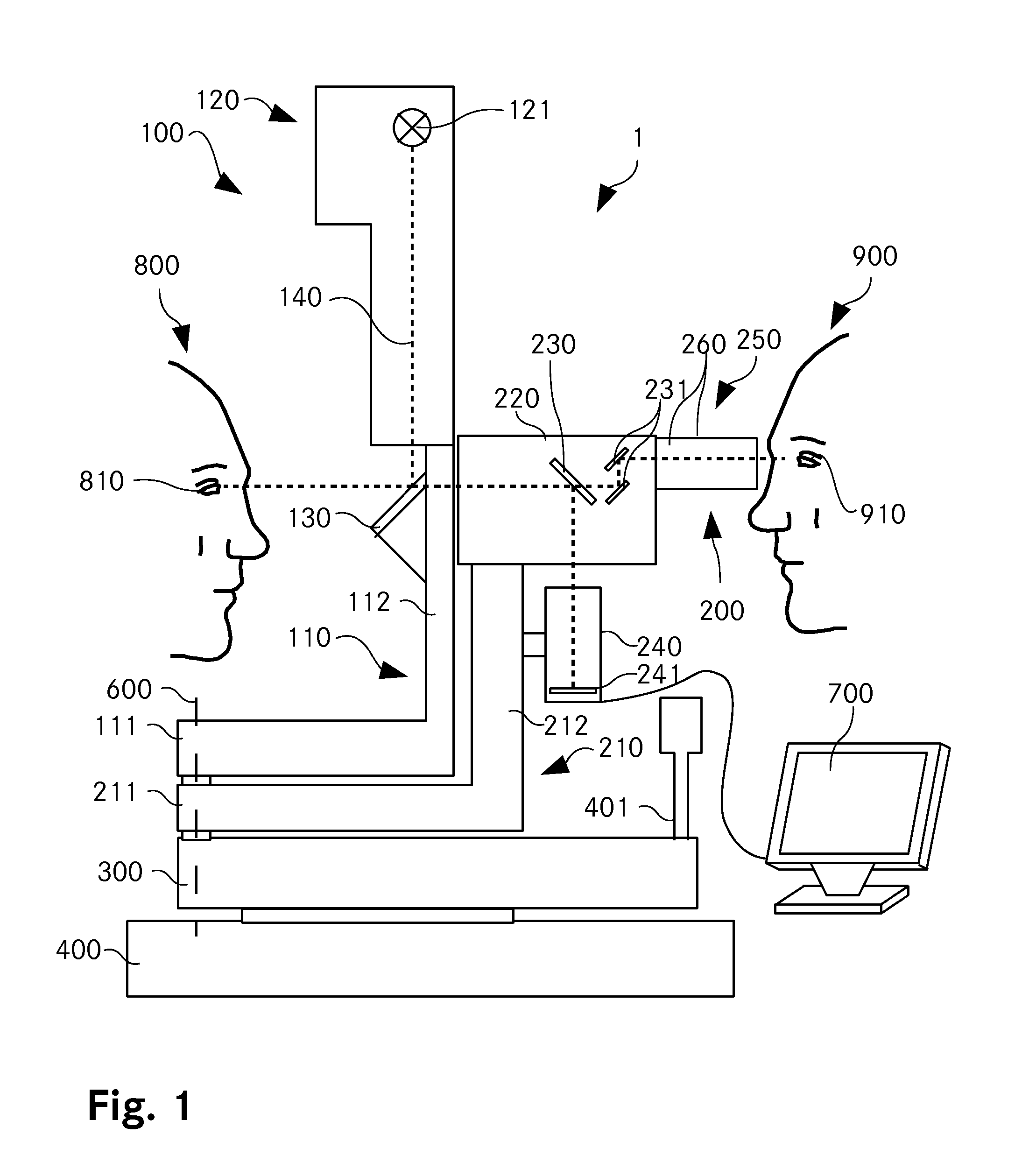
[0049]FIG. 2 shows a simplified sectional illustration through the optical unit and the image rendering unit of a device according to the invention for stereoscopically examining an eye;

second embodiment

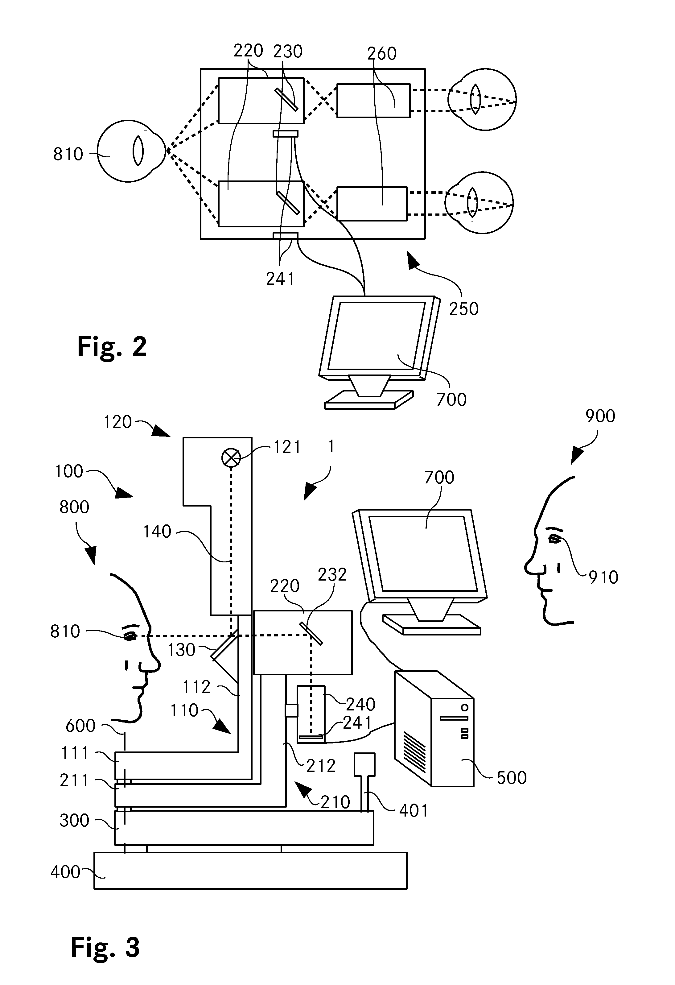
[0050]FIG. 3 shows a device according to the invention as per a first aspect of the invention;

third embodiment

[0051]FIG. 4 shows the device according to the invention in a side view; and

[0052]FIG. 5 shows an observation unit as an element detached from the microscope.

[0053]In principle, the same parts have been provided with the same reference signs in the figures.

[0054]Ways of Implementing the Invention

[0055]The term light ray used in the following text should not be understood as being restricted to a single light ray or to a photon; rather, it should also be understood to mean a light wave beam, which can represent an image.

[0056]FIG. 1 shows a device 1 for examining an eye, embodied as a slit lamp 1. The slit lamp 1 comprises an illumination unit 100, an optics part 220, an observation unit 200 which are mounted on a cross slide 300.

[0057]The cross slide 300 itself is mounted on a base plate 400, which can be embodied as a tabletop, and can be displaced in the x-, y- and z-directions. The slide 300 can be controlled by means of an operating element 401, which is arranged on same. Using ...


PUM


Abstract

A device for stereoscopic examination of an eye, in particular a slit-lamp microscope, comprises, according to a first aspect of the invention, a lens for generating two images of the eye, wherein the device comprises at least one image sensor for electronic recording of the two images. According to a second aspect of the invention, the device for examination of an eye, in particular the slit-lamp microscope, comprises a lens for generating one image, wherein it comprises an image sensor for electronic recording of one image, and a viewing unit with an image-reproducing unit for presenting the image, and an eyepiece for viewing the image.

Description

Technical field[0001]The invention relates to a device for examining an eye, having an optical unit for generating an image of the eye.PRIOR ART[0002]Slit-lamp microscopes are ophthalmological examination instruments, by means of which the eyes can be examined in monoscopic or stereoscopic fashion. For the purpose of stereoscopically observing an eye, known slit-lamp microscopes have an optical unit for generating two images of an eye and two eyepieces for stereoscopically observing the images, and also an illumination unit. The illumination unit is arranged on a vertically extending branch of a holder unit. The eye to be observed can be positioned in a plane extending approximately horizontally on one side of the holder unit. The illumination unit comprises an incandescent lamp, LEDs or similar illumination means for a slit illumination.[0003]Current devices for examining and / or treating an eye comprise a digital camera for recording an image and a screen for rendering the image.[0...

Claims


Application Information

Patent Timeline
Patent Type & Authority Applications(United States)
IPC IPC(8): A61B3/14
CPCA61B3/14A61B3/0083A61B3/132A61B3/135
Inventor TEIJIDO, JUAN MANUEL
Owner HAAG STREIT AG
Why Eureka
Try Eureka