
Oscillating mechanism with an elastic pivot and mobile element for transmitting energy

a technology of oscillating mechanism and mobile element, which is applied in the direction of escapements, gearworks, instruments, etc., can solve the problems of difficult positioning and requiring a qualified workforce or/and expensive apparatus, and the manufacture of springs is not very reproducible, and the mechanism incorporating them must be subject to the effect of for

Active Publication Date: 2013-07-11
NIVAROX FAR
View PDF13 Cites 53 Cited by
  • Summary
  • Abstract
  • Description
  • Claims
  • Application Information

AI Technical Summary

Benefits of technology

The invention proposes an alternative to traditional springs as means for maintaining oscillation in micromechanical and clock / watch making. The invention provides an oscillating mechanism for a timepiece movement that is flexible with a variable geometry and produced in a monobloc manner. The mechanism includes first and second rigid elements, with elastic restoring means that connect them. The elastic restoring means absorb, store, or set free energy during deformation. The invention also relates to a mobile element for transmitting energy and a timepiece movement comprising the oscillating mechanism. The technical effects of the invention include improved flexibility, reduced inertia, and improved energy transmission for faster pivoting of the escapement.

Problems solved by technology

Being delicate to implement, these components are in addition difficult to position and require a qualified workforce or / and expensive apparatus.
For this reason, manufacture of springs is not very reproducible and all the mechanisms incorporating them must be subject to regulation or adjustment.
Apart from the fact that their use in micromechanics is difficult, it is observed that precisely these properties of damping vibrations, and therefore of damping oscillations, run counter to the objective if, on the contrary, maintaining an oscillation is desired, with the minimum of damping.

Method used


Image

  • Oscillating mechanism with an elastic pivot and mobile element for transmitting energy
  • Oscillating mechanism with an elastic pivot and mobile element for transmitting energy
  • Oscillating mechanism with an elastic pivot and mobile element for transmitting energy

Examples


Embodiment Construction

[0031]The invention relates to the field of micromechanics and more particularly the field of clock / watch making.

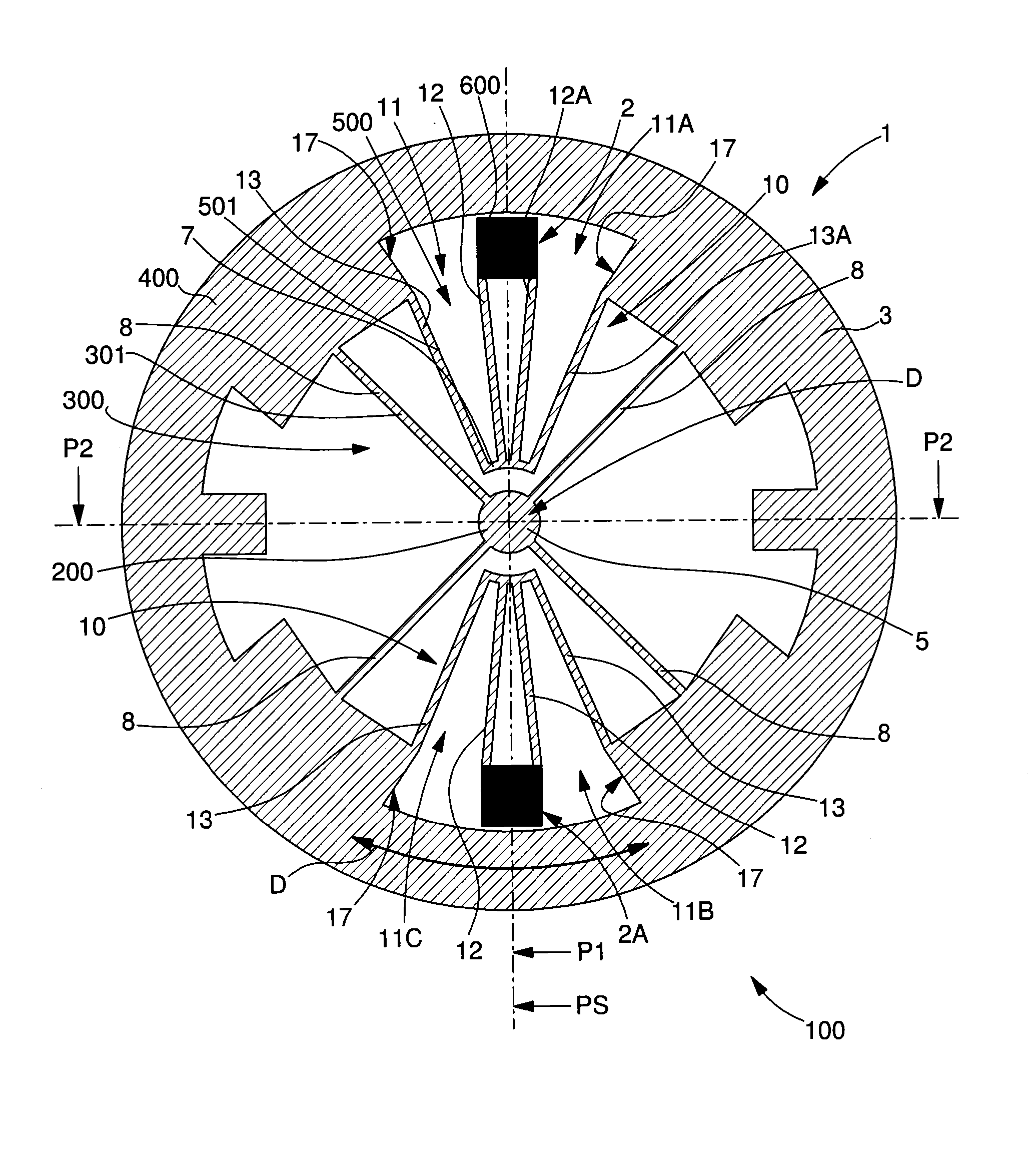
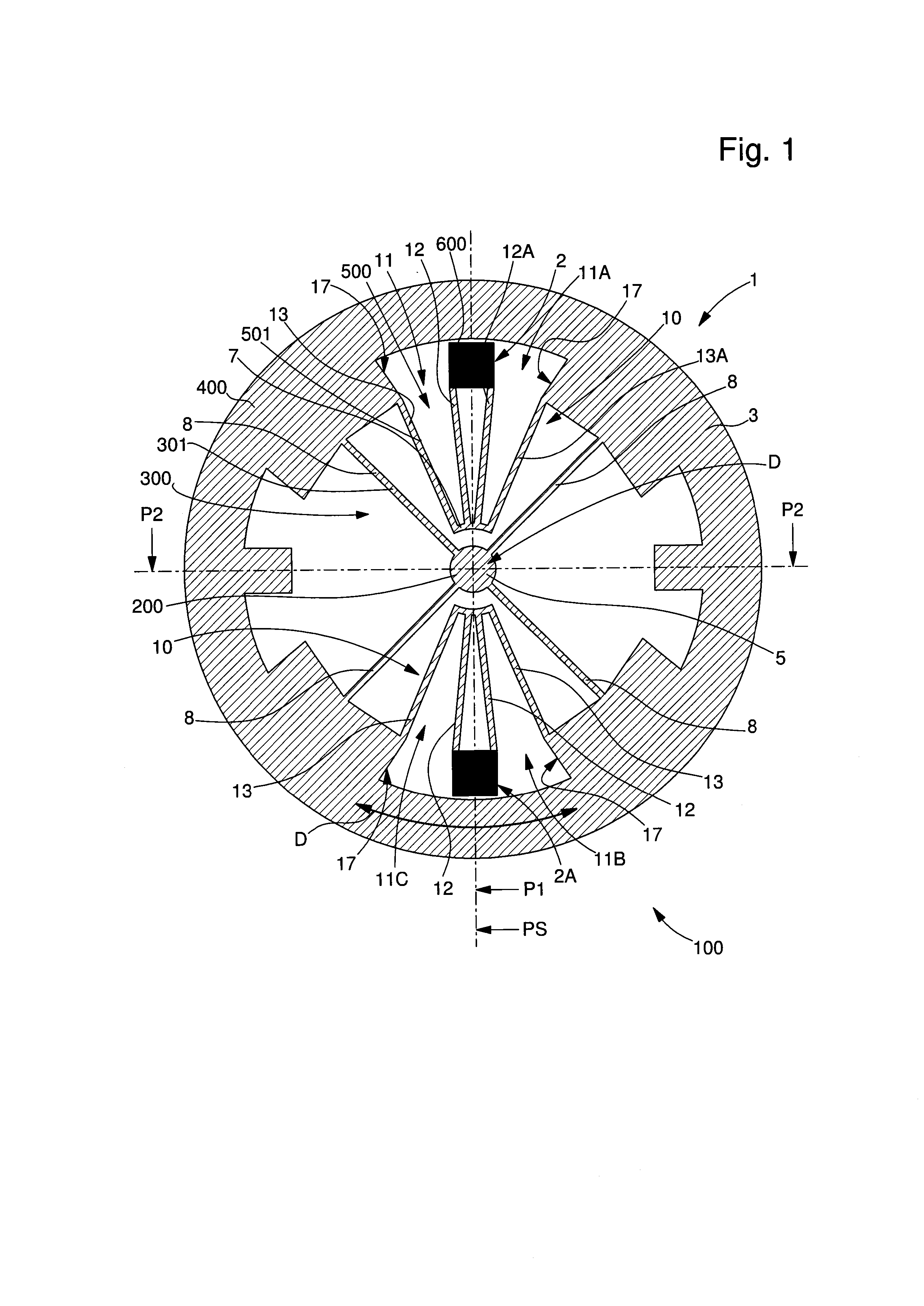
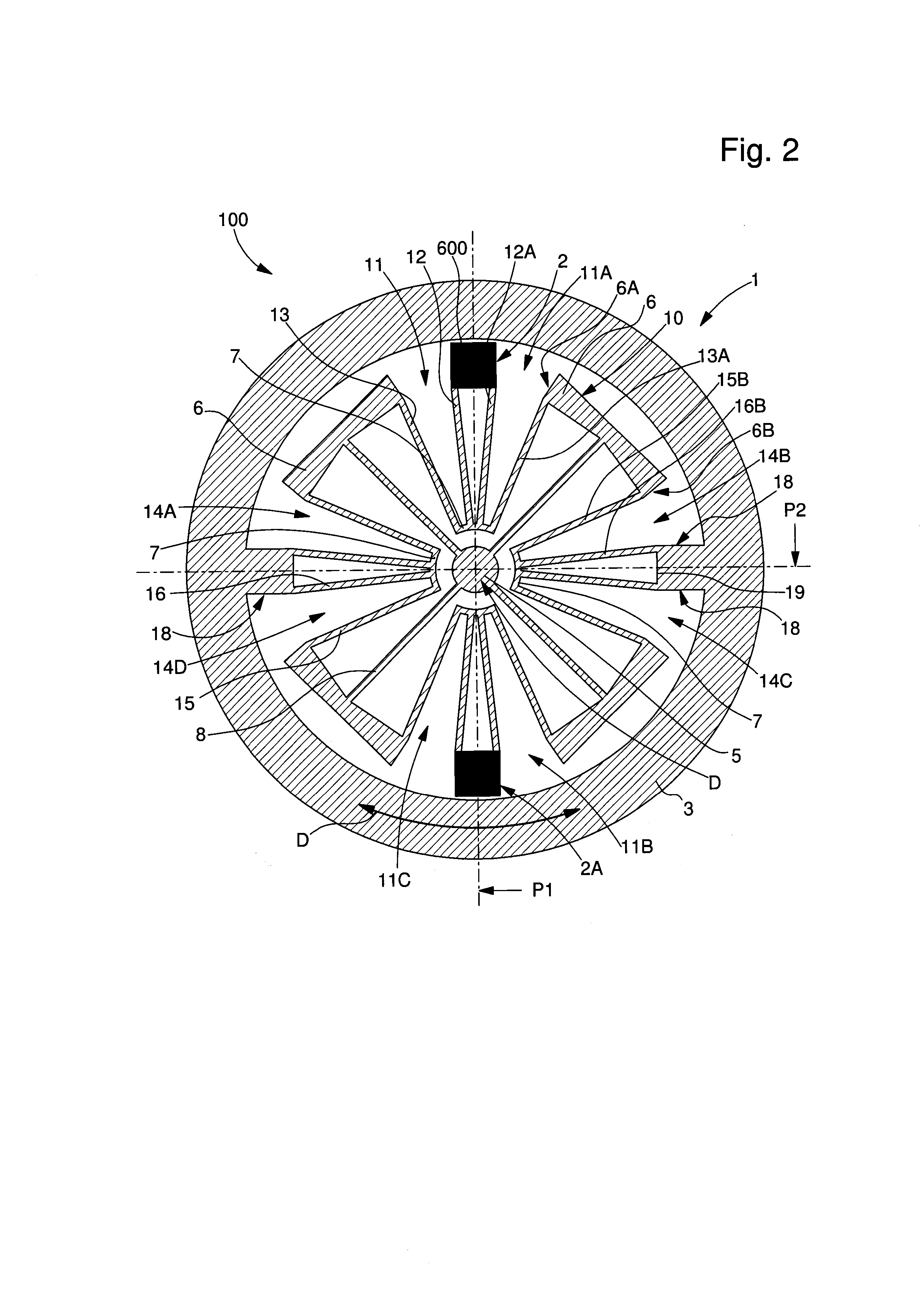
[0032]The invention relates to an oscillating mechanism 1 for a timepiece movement 1000. This oscillating mechanism 1 comprises a first rigid element 200 and a second rigid element 600, each one designed to be fixed on a different element of the movement 1000 and at least one of which is mobile relative to the other and pivots about a theoretical pivot axis D.

[0033]According to the invention, this oscillating mechanism 1 is flexible with a variable geometry, whilst being produced in a monobloc manner. It comprises first elastic restoring means 300 which produce a direct or indirect elastic connection between the first rigid element 200 and an intermediate rigid element 400. It comprises at least second elastic restoring means 500 which produce a direct or indirect elastic connection between this intermediate rigid element 400 and the second rigid element 600.

[0034]Further...


PUM


Abstract

An oscillating mechanism for a timepiece movement, including a first rigid element and a second rigid element, each one fixed on a different element of the movement and at least one of which is mobile relative to the other and pivots about an axis. The mechanism is monobloc and flexible with a variable geometry, and includes a first elastic restoring mechanism producing an elastic connection between the first rigid element and an intermediate rigid element, and a second elastic restoring mechanism producing an elastic connection between the intermediate element and the second rigid element, which all are coplanar according to one plane and configured to be deformed according to the plane.

Description

FIELD OF THE INVENTION[0001]The invention relates to an oscillating mechanism for a timepiece movement, comprising a first rigid element and a second rigid element, each one designed to be fixed on a different element of said movement and at least one of which is mobile relative to the other and pivots about a theoretical pivot axis.[0002]The invention also relates to a mobile element for transmitting energy for a timepiece movement, comprising such an oscillating mechanism, between at least one first emitter mobile element of said movement, on the one hand, and at least one second receiver mobile element of said movement, on the other hand, said oscillating mechanism allowing at least one degree of freedom by pivoting about said theoretical pivot axis.[0003]The invention also relates to a timepiece movement comprising such an oscillating mechanism.[0004]The invention also relates to a timepiece comprising such an oscillating mechanism.[0005]The invention also relates to the use of ...

Claims


Application Information

Patent Timeline
Patent Type & Authority Applications(United States)
IPC IPC(8): G04B17/00G04B15/00
CPCG04B13/025G04B15/14G04B17/063G04B17/00G04F7/0823G04B15/00G04B17/26G04B17/20G04B17/28G04B17/285G04B17/02G04B17/045
Inventor CUSIN, PIERRECHARBON, CHRISTIANVERARDO, MARCO
Owner NIVAROX FAR
Learn More