Thermally-Insulated Micro-Fabricated Atomic Clock Structure and Method of Forming the Atomic Clock Structure

a technology of atomic clocks and microfabricated fabricated parts, which is applied in the direction of atomic clocks used in electrical apparatus, pulse automatic control, electrical apparatus construction details, etc., can solve the problems of limited applications where atomic clocks can be commercially used, difficult to achieve, and operate with very little power

Active Publication Date: 2013-07-11
TEXAS INSTR INC
View PDF4 Cites 27 Cited by
  • Summary
  • Abstract
  • Description
  • Claims
  • Application Information

AI Technical Summary

Benefits of technology

The present invention relates to a thermally-insulated micro-fabricated atomic clock structure and a method of forming the atomic clock structure. The invention is about a way to create an atomic clock that uses a planar coil and a vapor cell containing alkali atoms and buffer atoms. The planar coil is designed to generate a magnetic field that aligns the magnetic moment of the alkali atoms with the direction of the magnetic field. The magnetic moment of the electrons in the alkali atoms precesses about the direction of the magnetic field, and this precessing is used to determine the frequency of the clock. The invention also includes a method for forming the atomic clock structure. The technical effect of the invention is to provide a more accurate and stable atomic clock that can be used in various applications such as navigation and time-based communication.

Problems solved by technology

Two of the drawbacks of conventional Larmor-based atomic clocks are size and cost, which then limit the types of applications where atomic clocks can be commercially utilized.
However, many of the applications for micro-fabricated atomic clocks require the clock to operate with very little power in an environment where the external temperature can range from, for example, −40° C. to +100° C. This is difficult to achieve because the VCSEL and the gas within the vapor cell must each be heated to operate within specific temperature ranges to ensure proper operation.

Method used


Image

  • Thermally-Insulated Micro-Fabricated Atomic Clock Structure and Method of Forming the Atomic Clock Structure
  • Thermally-Insulated Micro-Fabricated Atomic Clock Structure and Method of Forming the Atomic Clock Structure
  • Thermally-Insulated Micro-Fabricated Atomic Clock Structure and Method of Forming the Atomic Clock Structure

Examples


Embodiment Construction

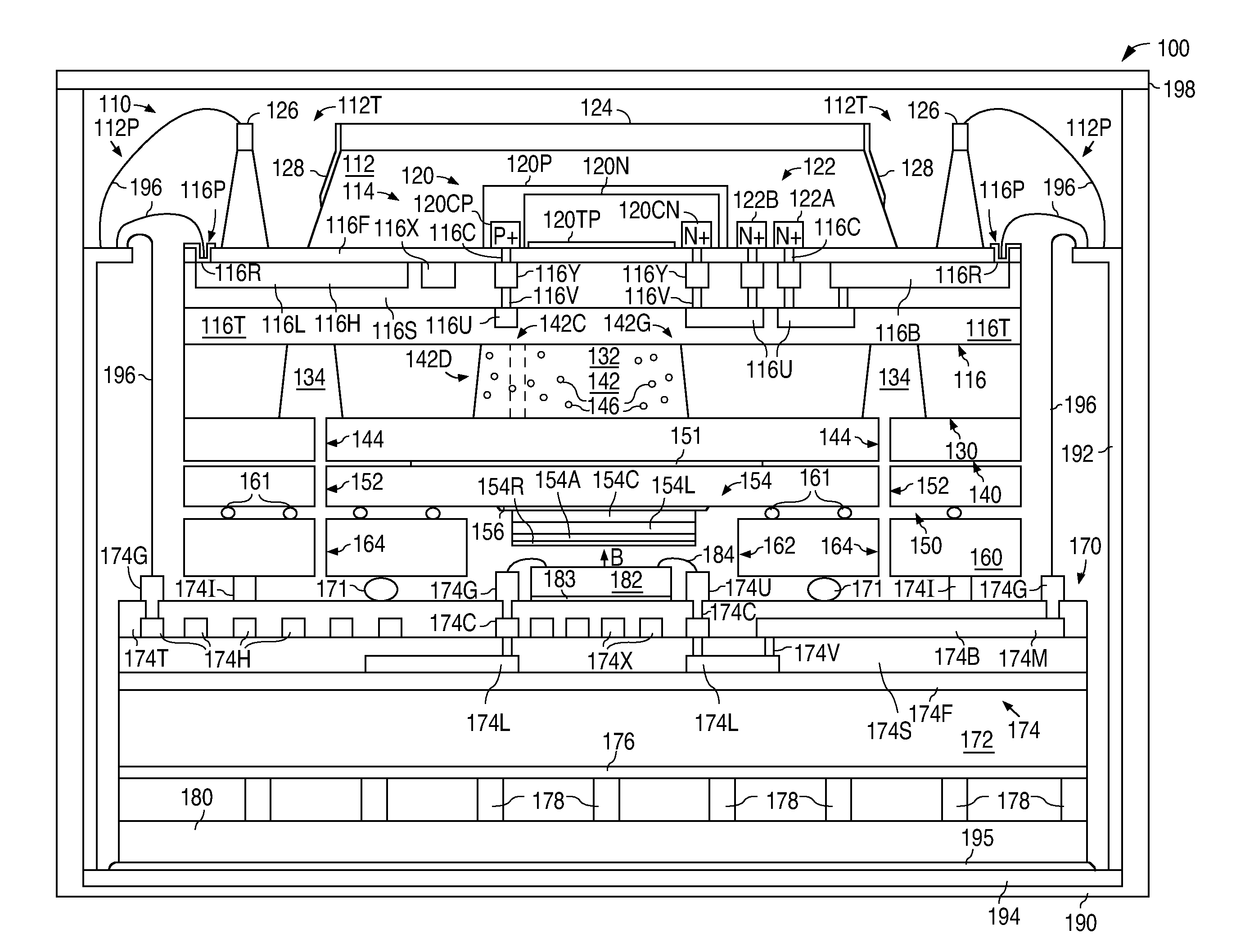
[0042]FIG. 1 shows a block diagram that illustrates an example of a thermally-insulated micro-fabricated atomic clock structure 100 in accordance with the present invention. As described in greater detail below, the present invention thermally insulates a micro-fabricated atomic clock structure so that the clock structure can operate with very little power in an environment where the external temperature can drop to −40° C., while at the same time maintaining the temperature required for the proper operation of the VCSEL and the gas within the vapor cell.

[0043]As shown in FIG. 1, clock structure 100 includes a photodiode structure 110 that has a substrate 112, a number of circuit elements 114 that lie within substrate 112, and a metal interconnect structure 116 that touches substrate 112. In the present example, substrate 112 is implemented with p− single-crystal silicon that has a device surface and an opposing non-device surface.

[0044]In addition, substrate 112 has a thermal barri...


PUM


Abstract

A micro-fabricated atomic clock structure is thermally insulated so that the atomic clock structure can operate with very little power in an environment where the external temperature can drop to −40° C., while at the same time maintaining the temperature required for the proper operation of the VCSEL and the gas within the vapor cell.

Description

BACKGROUND OF THE INVENTION[0001]1. Field of the Invention[0002]The present invention relates to atomic clocks and, more particularly, to a thermally-insulated micro-fabricated atomic clock structure and a method of forming the atomic clock structure.[0003]2. Description of the Related Art[0004]A planar coil is a coil where each loop of the coil lies within the same plane. A current flowing in a planar coil generates a magnetic field that is perpendicular to the plane. When an object with a magnetic moment is placed in a magnetic field, the magnetic field exerts a force on the magnetic moment that tries to align the magnetic moment with the direction of the magnetic field.[0005]Individual electrons have an intrinsic magnetic moment which can be thought of in the same manner as the magnetic moment that results from a current in a planar coil. As a result, when an electron is placed in a magnetic field, the magnetic field tries to align the intrinsic magnetic moment of the electron wi...

Claims


Application Information

Patent Timeline
IPC IPC(8): H05K7/00H01L31/0224H01L31/18
CPCH03L7/26H01L31/1804G04F5/14Y02E10/547H01L31/103H01L31/00H01L31/022408H01L2224/48091H01L2224/49107H01L2924/16195H01L2924/00014H01L31/024H01L31/18
Inventor HOPPER, PETER J.FRENCH, WILLIAMMAWSON, PAULHUNT, STEVENPARSA, ROOZBEHFALLON, MARTINGABRYS, ANNPAPOU, ANDREI
Owner TEXAS INSTR INC
Why Eureka
Try Eureka