
Oil skimmer assembly and system

a technology of oil skimmer and assembly, which is applied in the direction of water cleaning, separation process, filtration separation, etc., can solve the problems of oil spilling into the waterways, the general impracticality of shallow water devices, and the time-consuming and costly use of devices

Inactive Publication Date: 2013-04-18
BOH BROS CONSTR CO
View PDF2 Cites 3 Cited by
  • Summary
  • Abstract
  • Description
  • Claims
  • Application Information

AI Technical Summary

Benefits of technology

The invention is an oil skimming system that allows operators to safely and quickly skim large quantities of oil from water without having to enter the polluted waters. It also works optimally to collect only the desired skimmed matter and prevents the collection of unwanted debris. This system is less labor-intensive and requires no special clothing for the operator.

Problems solved by technology

One long standing problem with the drilling and transporting of oil has been the spilling of oil into the waterways and water bodies in which the oil drilling and oil transporting take place.
However, once the oil reaches the shoreline or beach area those devices that are useful in deep water are generally impractical in shallow water.
Although such prior art skimmers can skim some of the oil from the water they are time consuming and costly to use.
In addition, they are highly inefficient, particularly if being used in what that is choppy or effected by tides.
Such a suit is hot to wear and makes the skimming operation more difficult for the operator to perform.
Because of the heat conditions, as well as hydrocarbon vapors emitted from the oil polluted water, an operator can only work for short periods of time before the operator must take a break to avoid health and fatigue problems.
Still further these devices are only able to skim small quantities of oil during a given time period.
Thus, their use to clean up large oil spills makes such cleanup operations labor intensive, time consuming, inefficient, and very expensive.

Method used


Image

  • Oil skimmer assembly and system
  • Oil skimmer assembly and system
  • Oil skimmer assembly and system

Examples


Embodiment Construction

[0021]The oil skimmer assembly and system of this invention can be used to skim a wide variety of matter from a fluid surface. This can include skimming particulates or other material from the surface of a sludge pond or waste pit. However, without any intent to limit the scope of this invention, the preferred embodiments of the invention are described making reference to the skimming of oil from a water surface.

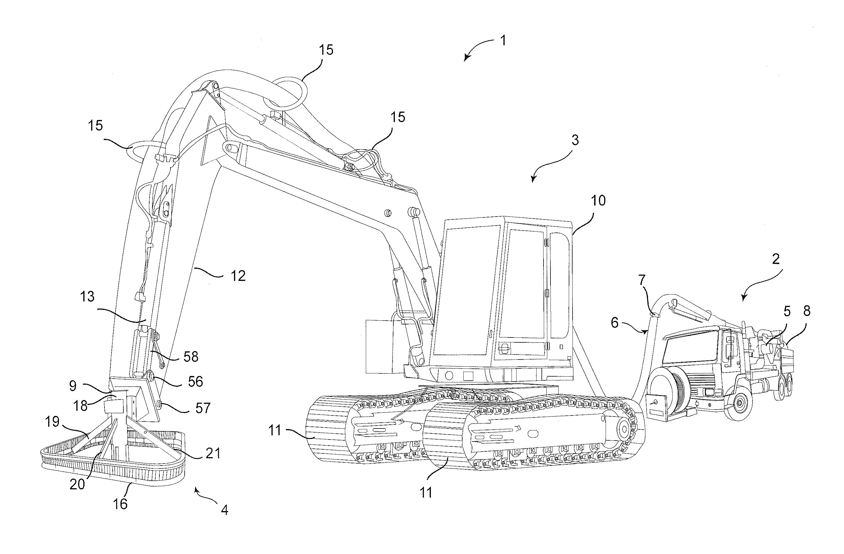
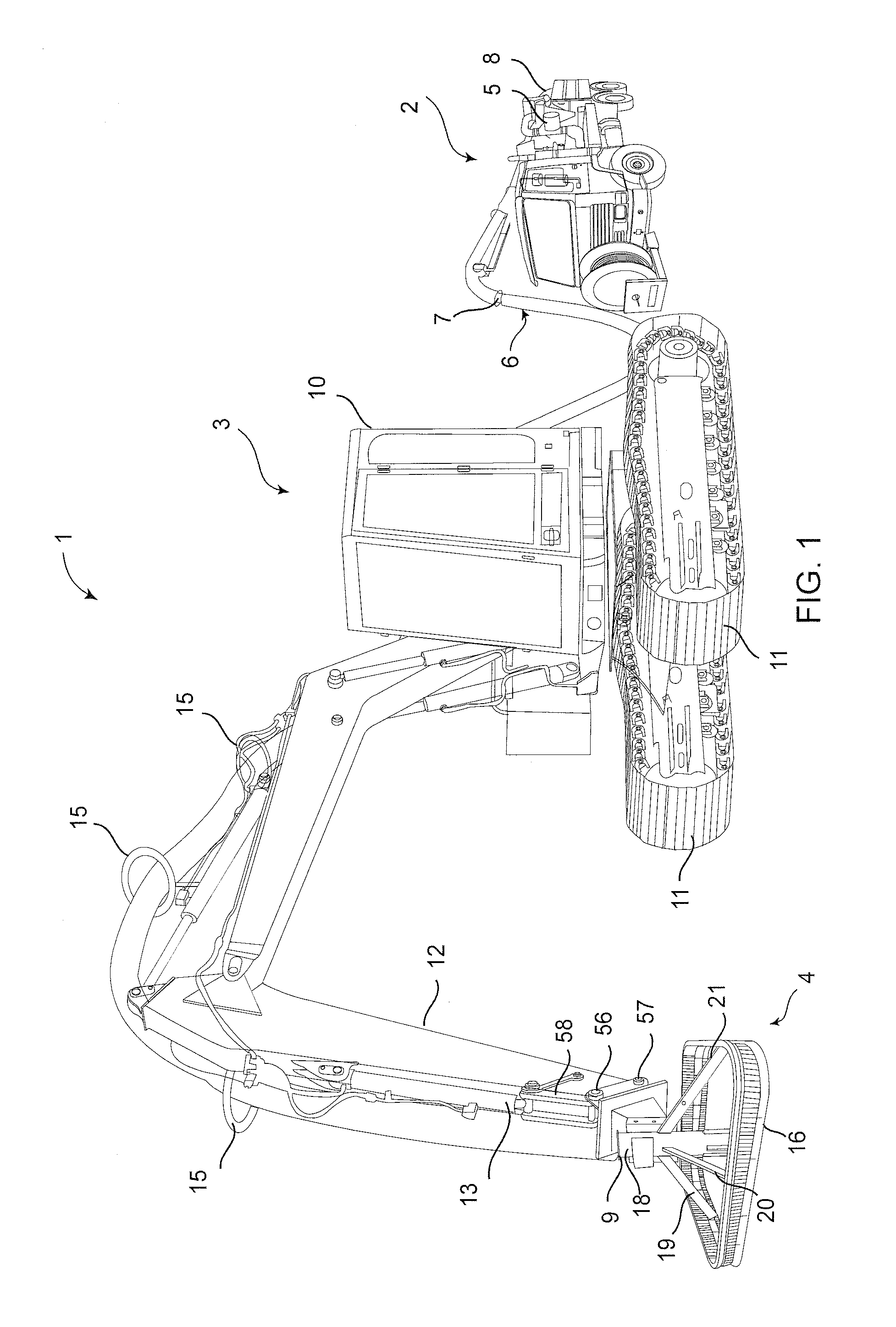
[0022]The system includes three basic elements: a pump with an intake hose attached to the intake port of the pump and a discharge hose attached to the discharge port of the pump, an articulating and extendable extension member mounted on vessel or land vehicle, and the oil skimmer assembly affixed to the extension member and operatively attached to the intake hose. If the oil cleanup is to be conducted from the shore line, in order to obtain maximum operational flexibility and mobility it would be preferred that the pump on a conventional vacuum truck be used and the hydrau...


PUM

PropertyMeasurementUnit
Pressureaaaaaaaaaa
Distanceaaaaaaaaaa
Surface areaaaaaaaaaaa

Abstract

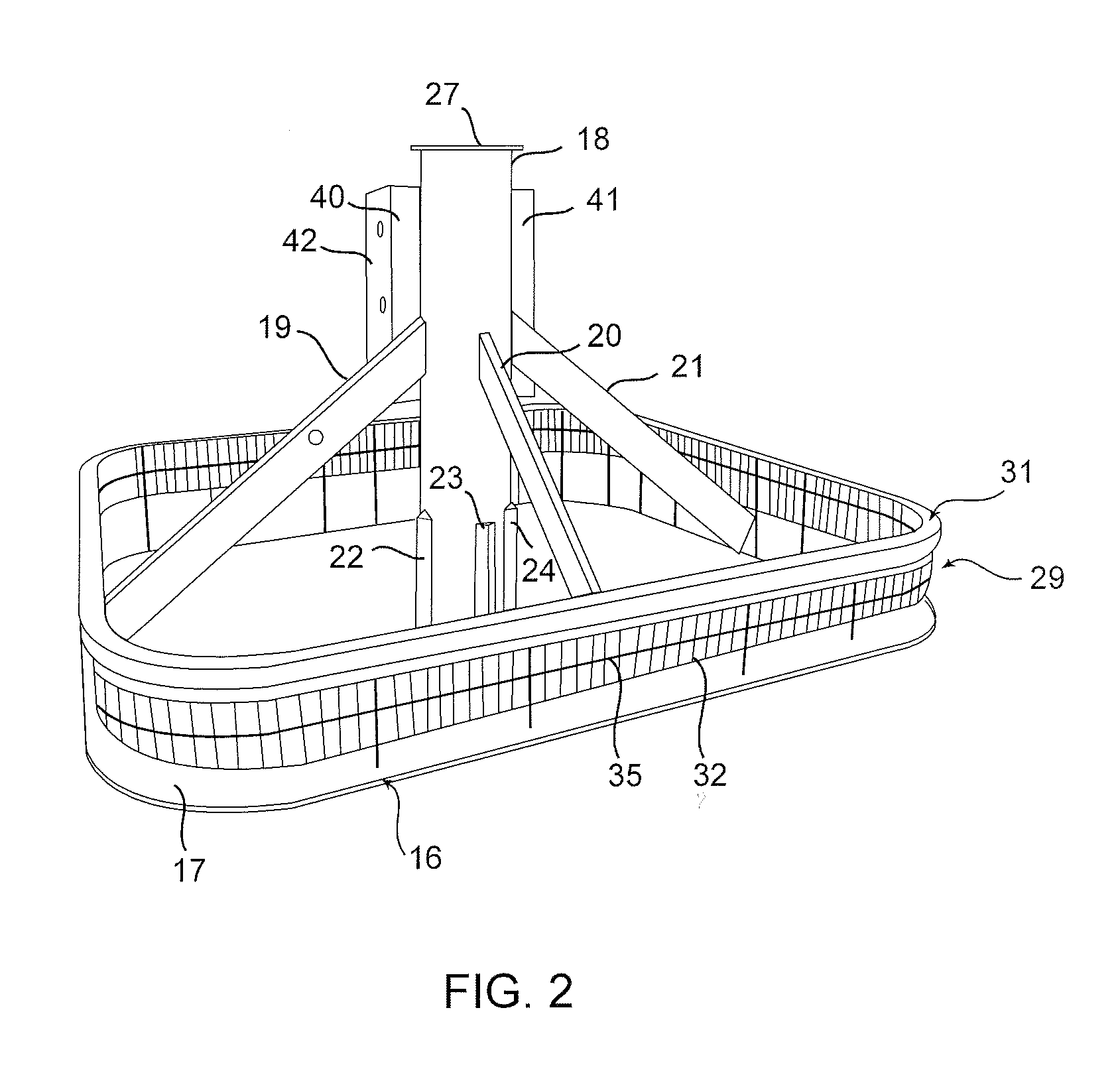
An oil skimmer system including a vacuum truck having a pump with a vacuum hose attached at one end to the pump intake port to create a suction at the opposite or intake end of the vacuum hose to which a suction tube is operatively attached at its discharge end, and mounted on an articulating and extendable arm of a backhoe an oil skimmer assembly comprising (a) a skimmer plate having an upper flat surface, (b) a debris guard vertically mounted about the suction tube intake end, (c) the suction tube affixed by one or more struts to extend perpendicularly above the plate upper surface with the suction tube intake end positioned near the plate upper surface, and (d) a connecting adaptor affixed to the suction tube and configured to fixedly attach the oil skimmer assembly to the backhoe arm to enable positioning the oil skimmer assembly into the oil containing surface area of a body of water.

Description

BACKGROUND OF THE INVENTION[0001]1. Field of the Invention[0002]This invention relates in general to apparatus for skimming fluids or other material from the surface of a water body, and more particularly to apparatus for skimming oil and other similar fluids from the surface of inland or shallow waters of a lake, bay, cove, port, gulf or ocean.[0003]2. Prior Art[0004]One long standing problem with the drilling and transporting of oil has been the spilling of oil into the waterways and water bodies in which the oil drilling and oil transporting take place. In response to this problem various devices, such as oil booms and oil skimmers, have been attached to a variety of boats. However, once the oil reaches the shoreline or beach area those devices that are useful in deep water are generally impractical in shallow water. To skim the oil from the shallow water areas one technique has been the use of a vacuum truck having a long 50′-200′ six-inch to ten-inch vacuum hose provided with a...

Claims


Application Information

Patent Timeline
IPC IPC(8): E02B15/04
CPCE02B15/048Y02A20/204
Inventor LAMONTE, LARRY R.
Owner BOH BROS CONSTR CO
Learn More