Cable Cord Retractor

a cable and retractor technology, applied in the direction of spring-loaded loop arrangements, gravity-loaded arrangements, etc., can solve the problems of premature breakage of cord wires, rapid wear and tear of cables,

Active Publication Date: 2013-03-21
CRESTRON ELECTRONICS
View PDF2 Cites 28 Cited by
  • Summary
  • Abstract
  • Description
  • Claims
  • Application Information

AI Technical Summary

Benefits of technology

[0010]In a second aspect of the invention, a cord retractor comprises a first frame having first and second frame ends; and first and second laterally spaced tracks extend between and are fixed to the frame ends. The retractor further includes a second frame having first and second end portions. The first end portion is coupled to the second frame end in such a manner that the second frame is configured to pivot relative to the first frame. A first pair of pulleys is rotatable on a first axis and being disposed in the first and second laterally spaced tracks for sliding motion between the first and second frame ends. A slideable block having a bracket is coupled in-between the first pair of pulleys and at least one spring spool. The at least one spring spool is mounted at the first frame end and the slideable block is disposed in the first and second tracks. A second pair of pulleys includes a gear, which is rotatable on a second axis. The second pair of pulleys is journalled at the second frame end of the first frame. A cord has an intermediate storage section in which one end of the storage section is fixed to one of the first and second frame ends and the other end of the storage section comprises a free end that extends from the first frame through the second frame and beyond the second end portion. The cord storage section is at least partially wound over the first and second pair of pulleys. A damper is coupled to one of the second pair of pulleys, which engages one of the pulleys to rotate about the second axis to damp the rotary motion of one of the second pair of pulleys in such a manner that the intermediate storage section is in tension during retraction and withdrawal. Upon a tensile force acting on the free end of the cable, the first ...

Problems solved by technology

It wears out rapidly and must be replaced after a relatively short period of use.
Some cord retractors operate...

Method used


Image

  • Cable Cord Retractor
  • Cable Cord Retractor
  • Cable Cord Retractor

Examples


Embodiment Construction

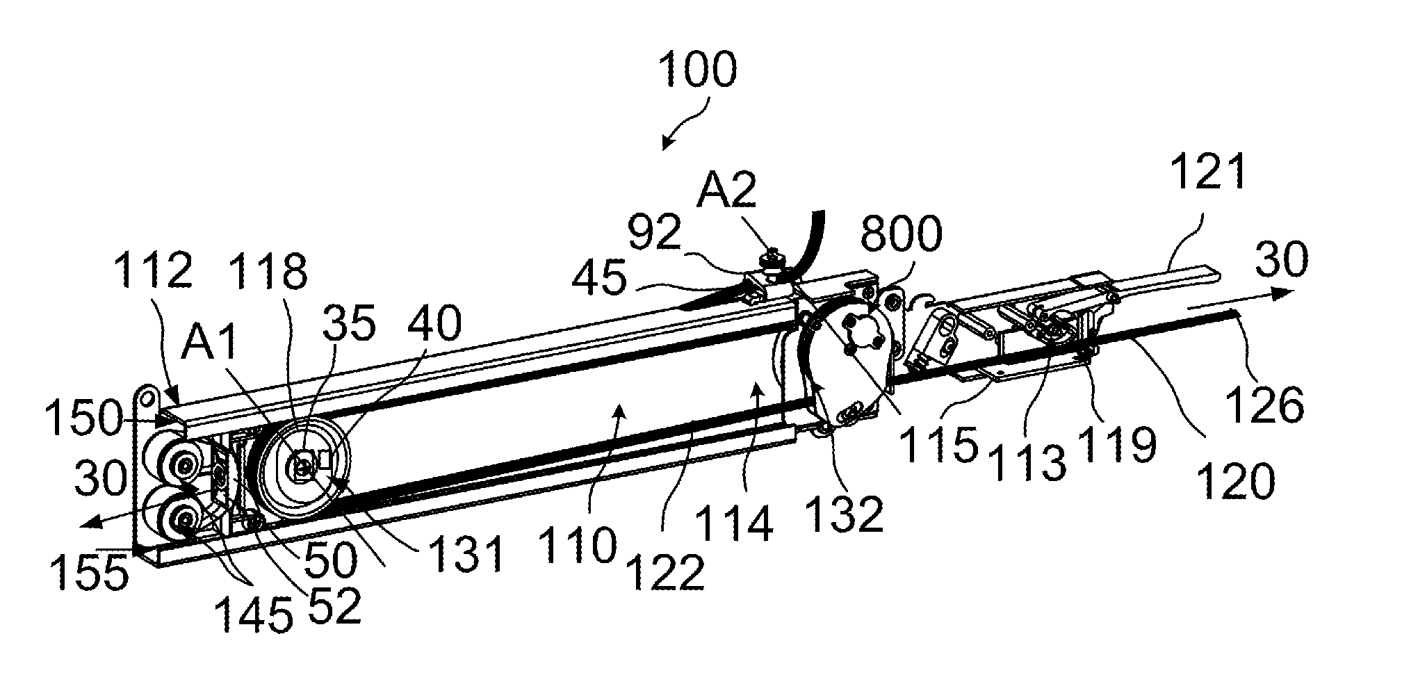
[0119]The present invention relates to a device for managing a cable. More particularly, the invention relates to a cable retractor for facilitating the withdrawal and retraction of a length of cable in such a manner that the cable remains in tension during the withdrawal and retraction.

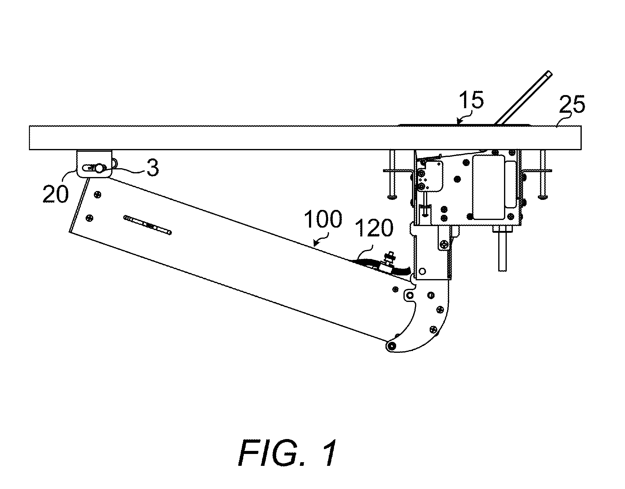
[0120]FIG. 1 illustrates a cable retractor 100 for facilitating the withdrawal and retraction of a length of cable 120. The cable retractor 100 is mounted to a flip top control center 15, which is flush mounted to a tabletop 25. The flip top control center 15 includes a compartment to keep interface cables at the ready to be plugged into computers, AV sources, and a host of other devices. The cable retractor 100 provides for extensive connectivity is an easy pull out cable storage mechanism to support a wide range of applications and signal types. When the cable 120 is not in use, the user end of each cable 120 stows neatly within the flip top control center 15 compartment while excess cable 120 simp...


PUM


Abstract

A retractor for storing a length of cord that includes a first and second pair of pulleys mounted at opposite ends of a frame. An intermediate section of a cord is stored in the frame. The stored cord section is at least partially wound over the pair of pulleys, and one pair of pulleys is slidably mounted for motion toward the other pair of pulleys. A damper is coupled to one of the second pair of pulleys, which engages the pulley to rotate about an axis to damp the rotary motion of one of the second pair of pulleys in such a manner that the intermediate storage section is in tension during retraction and withdrawal. The retractor further includes a cable system that is coupled to a slot formed on the second frame end and configured to provide a substantially consistent retraction speed of the cord.

Description

BACKGROUND OF THE INVENTION[0001]1. Technical Field[0002]The present invention relates to a mechanism for storing and retracting a cable. More particularly, the invention relates to a cable retractor for facilitating the withdrawal and retraction of a length of cable in such a manner that the cable remains in tension during the withdrawal and retraction.[0003]2. Background Art[0004]Various types of electronic instrumentation are remotely controlled or are coupled with a handset or hand-held controller by a multi-wire electric cord extending to some type of electronic box. For example, a telephone handset or a hand-held microphone and control are connected by multi-wire electric cords to relatively fixed positioned electronic devices, such as a telephone body or a recorder. A hand controller or handset for an aircraft passenger entertainment system may be connected by an electric cable to an electronic control box. The handset, which is preferably stored in a position closer to the e...

Claims


Application Information

Patent Timeline
IPC IPC(8): B65H75/30B65H75/48
CPCB65H75/30B65H75/486B65H2701/34H02G11/003B65H75/368
Inventor FELDSTEIN, GEORGECAMPAGNA, MICHAEL
Owner CRESTRON ELECTRONICS
Why Eureka
Try Eureka