
Replaceable staking insert assembly and method

a technology of inserts and assembly, which is applied in the direction of forging/pressing/hammering apparatuses, marine propulsion, vessel construction, etc., can solve the problem of a limit on the number of attachments

Active Publication Date: 2013-02-28
GENERAL ELECTRIC CO
View PDF3 Cites 1 Cited by
  • Summary
  • Abstract
  • Description
  • Claims
  • Application Information

AI Technical Summary

Benefits of technology

The present application describes a rotor assembly with a blade positioned within an axial slot on a rotor rim, which is secured with a staking insert and a shim. The staking insert has a base and a projection that is positioned within the first staking recess of the rotor and the blade, respectively. The staking insert is then deformed to secure the blade in place. The technical effects of this design include improved efficiency and stability of the rotor assembly and reduced likelihood of blade displacement during operation.

Problems solved by technology

There are a finite number of attachments due to a limited number of viable staking locations about the rotor wheel.

Method used


Image

  • Replaceable staking insert assembly and method
  • Replaceable staking insert assembly and method
  • Replaceable staking insert assembly and method

Examples


Embodiment Construction

[0016]The present application will now be described more fully hereinafter with reference to the accompanying drawings, in which several embodiments of the application are shown. Like numbers refer to like elements throughout the drawings.

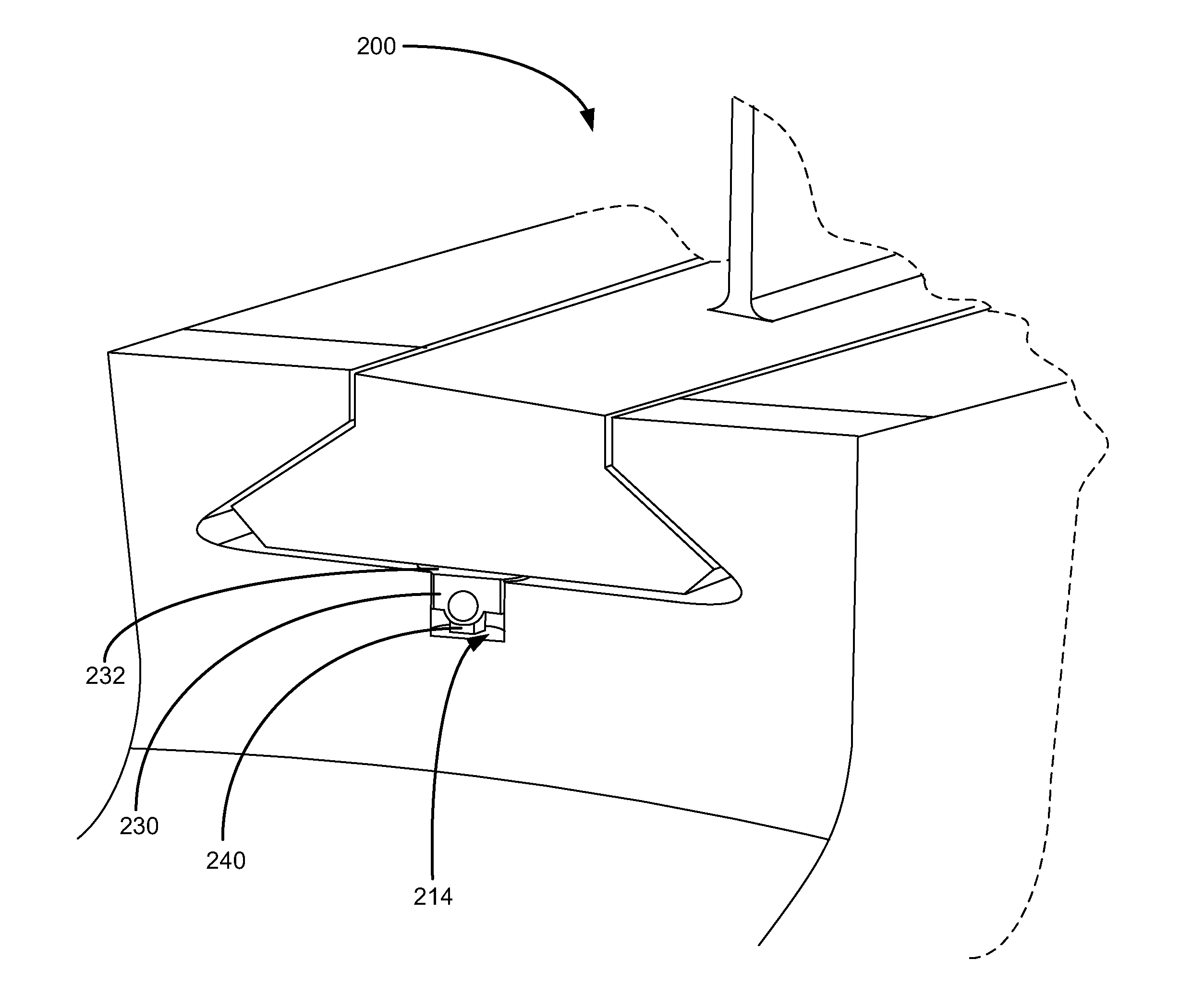
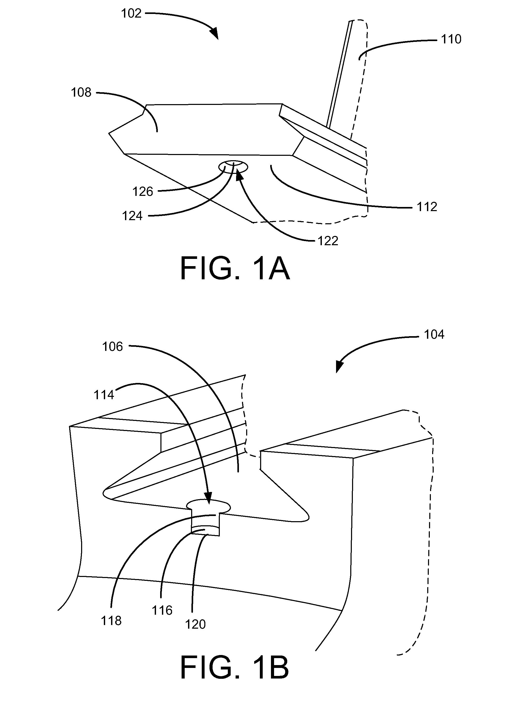
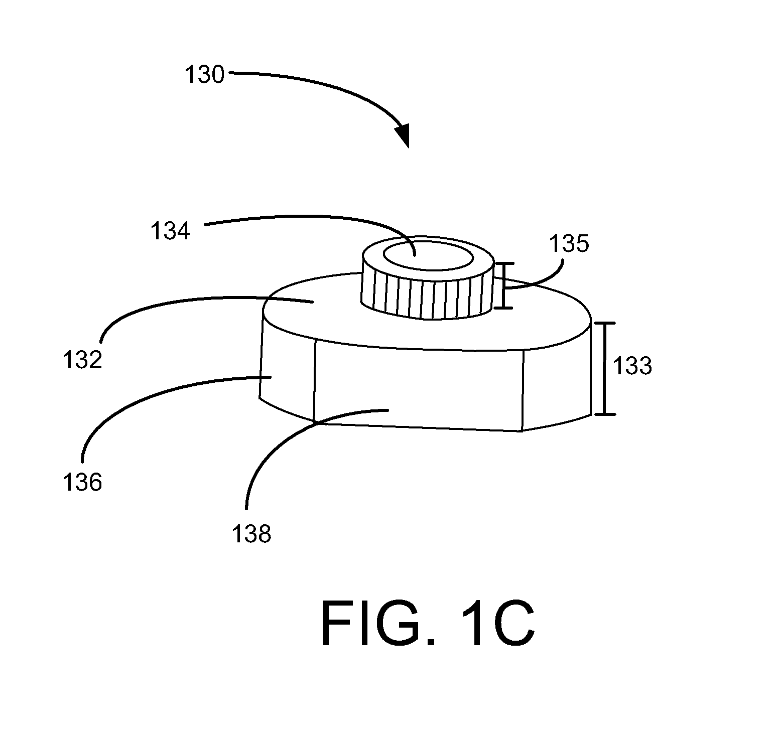
[0017]In one aspect, a rotor assembly is provided. FIGS. 1A and 1B show a rotor blade 102 and a rotor 104, respectively, which are components of a rotor assembly. The rotor 104 may include at least one axial slot 106 positioned about the rim of the rotor 104. The axial slot 106 may be any shape known in the art. In certain embodiments, the axial slot 106 has a dovetail-like shape. The axial slot 106 may include a first staking recess 114 positioned therein. In some embodiments, the first staking recess includes a base and at least one sidewall. In one embodiment, the first staking recess 114 is positioned at one end of the axial slot 106 and has a base 116 and a concave sidewall 118 that defines an axial opening 120. However, other shapes of the fi...


PUM

PropertyMeasurementUnit
thicknessaaaaaaaaaa
thicknessaaaaaaaaaa
thicknessaaaaaaaaaa

Abstract

A rotor assembly. The rotor assembly may include a rotor, at least one axial slot positioned about the rim of the rotor having a first staking recess positioned therein, a blade positioned within each of the axial slots having a second staking recess positioned therein, a staking insert having a base portion and a projection extending therefrom with the base portion being disposed within the first staking recess and the projection being disposed within the second staking recess, and a shim positioned within the first staking recess adjacent to the base portion, opposite the projection, of the staking insert. The first staking recess retains the staking insert while the projection of the staking insert retains the blade in both the aft and forward directions.

Description

TECHNICAL FIELD[0001]The present application relates generally to a replaceable staking insert assembly for the retention of a wheel attachment, and more particularly relates to a replaceable staking insert assembly for a blade mounted on a compressor rotor.BACKGROUND OF THE INVENTION[0002]Gas turbine systems generally include a compressor rotor having a number of stages. Air flowing into the compressor is compressed at each stage. Each stage includes a number of rotor buckets or blades mounted to a rim of a rotor wheel or a disk in a spaced relationship. A typical compressor rotor may have dozens of rotor blades mounted thereon.[0003]Generally described, each blade may have a dovetailed portion that interlocks with a dovetail region of the rim to secure the blade to the rotor. The blade dovetails may be secured to the rotor via a process called “staking ” Specifically, the rotor blade is placed within the rim slot and then “staked” into place at both ends by deforming the metal mat...

Claims


Application Information

Patent Timeline
Patent Type & Authority Applications(United States)
IPC IPC(8): F01D5/32B23P15/04
CPCF01D5/30F01D5/3007Y10T29/49321F01D5/326F01D5/323
Inventor AGARAM, SUKUMARRAO, NARASIMHA KV
Owner GENERAL ELECTRIC CO
Learn More