
Work Vehicle

a technology for working vehicles and vehicles, applied in vehicle sub-unit features, anti-theft devices, instruments, etc., can solve the problems of limiting the precision of authentication, more difficult to change settings,

Active Publication Date: 2013-01-31
KUBOTA LTD
View PDF3 Cites 58 Cited by
  • Summary
  • Abstract
  • Description
  • Claims
  • Application Information

AI Technical Summary

Benefits of technology

The patent describes a new invention with certain features and benefits. The "technical effects" of the patent are the benefits and improvements that come from using these features. These benefits can be summarized by the R&D personnel.

Problems solved by technology

In view whereof, changing the mode of operation, as disclosed in JP 2010-013060 A, presumably renders it more difficult for a setting to be changed; however, as in JP 2010-013060 A, the screen is switched when the operation input unit is press-operated briefly, and a move is made to a screen making it possible to change a setting when the operation input unit is press-operated for a long time; even though the inputted content is confirmed by the elapsing of a period of time thereafter, it is impossible to avoid a false setting, and there remains room for improvement.
However, performing the authentication based on the number of iterations where a single switch is operated, as in the configuration of JP 2005-255134 A, also has limitations on enhancing the precision of the authentication, and there remains room for improvement.

Method used


Image

  • Work Vehicle
  • Work Vehicle
  • Work Vehicle

Examples


first embodiment

(Overall Configuration)

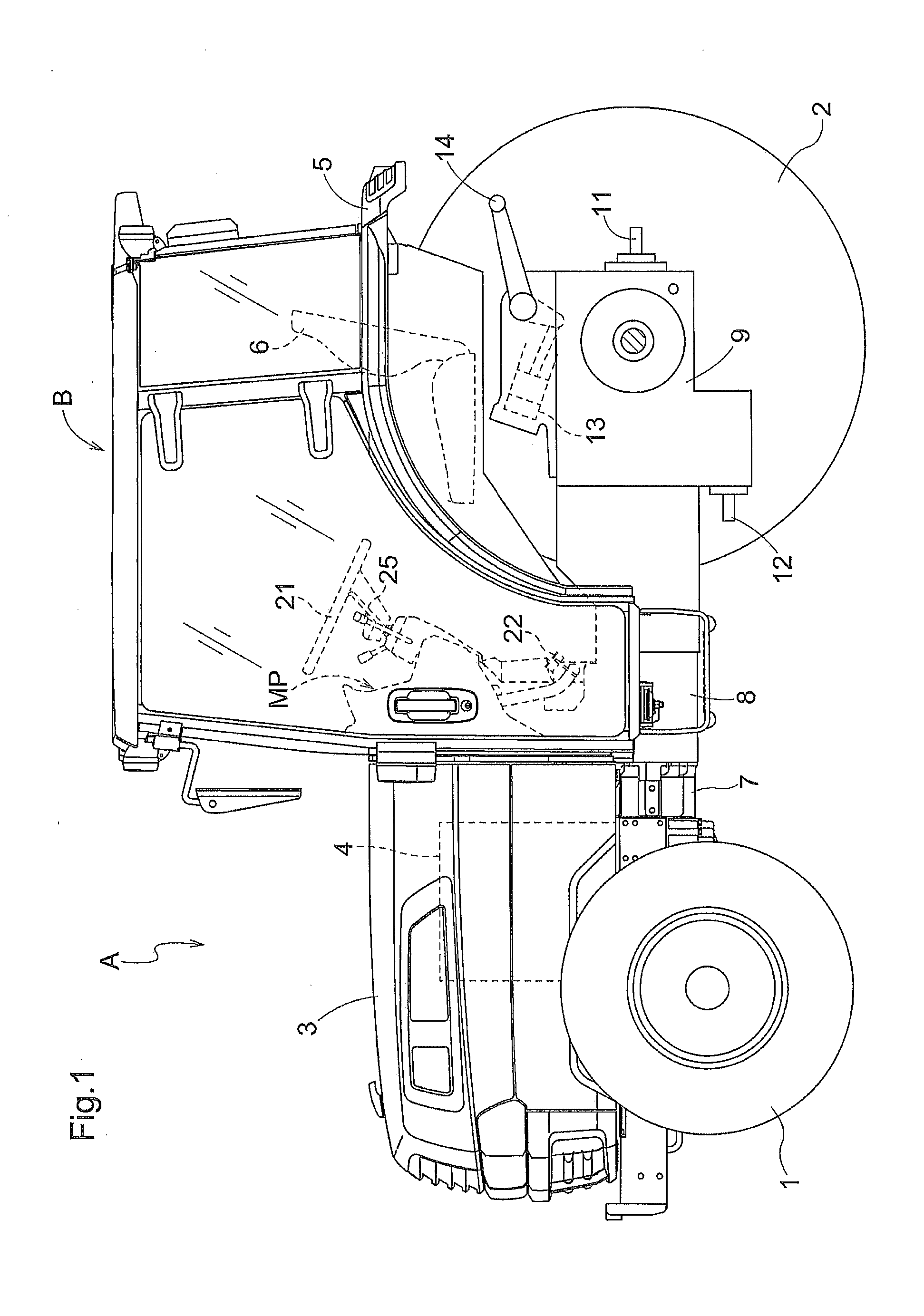
[0080]As shown in FIG. 1, the tractor is configured to comprise a pair of right / left front vehicle wheels 1 and a pair of right / left rear vehicle wheels 2, each acting as a travel device for a travel vehicle body A; a diesel engine 4 housed within an engine hood 3 of a front part of the travel vehicle body A; an operation seat 6 arranged at a middle position between right and left rear wheel fenders 5 for constituting an operation unit; and a cabin B for surrounding the operation unit.

[0081]In the tractor, a clutch housing 7, a hydrostatic stepless speed change device (HST) 8 and a transmission case 9 are connected one after another in the stated sequence toward a rear side of the engine 4. The transmission case 9 is arranged under the operation seat 6. These components form a transmission system for transmitting drive force from the transmission case 9 to the right / left front vehicle wheels 1 and the right / left rear vehicle wheels 2, to thereby form a four-wh...

second embodiment

[0137]A second embodiment of a work vehicle will be described next, with reference to FIGS. 12 to 18. In this embodiment as well, description will be made with reference to a tractor as an example of the work vehicle.

(Overall Configuration)

[0138]As shown in FIG. 12, the tractor is configured to comprise a pair of right / left front vehicle wheels 101 and a pair of right / left rear vehicle wheels 102, each acting as a travel device for a travel vehicle body A; a diesel engine 104 housed within an engine hood 103 of a front part of the travel vehicle body A; an operation seat 106 arranged at a middle position between right and left rear wheel fenders 105 for constituting an operation unit; and a cabin B for surrounding the operation unit.

[0139]In the tractor, a clutch housing 107, a hydrostatic stepless speed change device (HST) 108 and a transmission case 109 are connected one after another in the stated sequence toward a rear side of the engine 104. The transmission case 109 is arrange...


PUM


Abstract

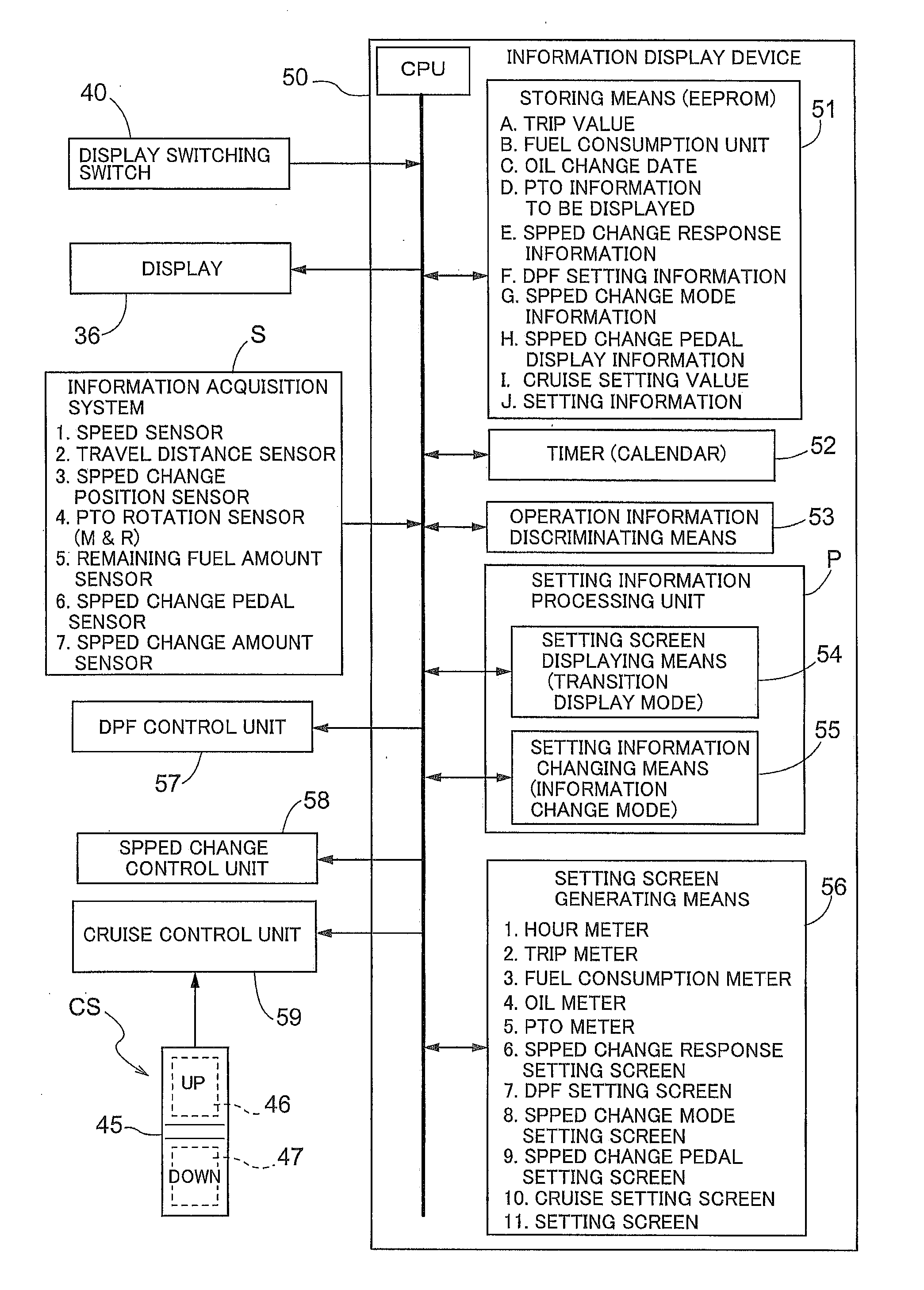
A work vehicle is disclosed with an information displaying device preventing set information corresponding to a setting screen displayed on a display from being erroneously changed even while permitting an operation for switching to and displaying one among a plurality of set screens on the display. A setting information processing unit of the information displaying device includes setting screen displaying means for switching the setting screen by the input of a first operation information item and displaying same in a transition display mode, and setting information changing means for performing a process in an information change mode for permitting a change to the set information corresponding to the setting screen, by inputting of a second operation information item. When it is determined that the second operation information item is inputted in the information change mode, a process for restoring the transition display mode from the information change mode is performed.

Description

BACKGROUND OF THE INVENTION[0001]1. Field of the Invention[0002]The present invention relates to a work vehicle such as a tractor.[0003]2. Description of the Related Art[1] In a work vehicle, a setting screen selected by a setting information processing unit provided to an information displaying device thereof from among a plurality of set screens corresponding to a plurality of information items is displayed on a display, and the set information corresponding to the selected setting screen is changed.[0004]For example, Japanese Laid-open Patent Publication 2009-143456 (JP 2009-143456 A) discloses a configuration comprising a display (a display unit in JP 2009-143456 A) for displaying various different information items of a vehicle body, a switch operational tool for switching the screen displayed on the display, and a setting operational tool for performing various different settings.[0005]In JP 2009-143456 A, a plurality of basic screens can be switched by a switch operational to...

Claims


Application Information

Patent Timeline
Patent Type & Authority Applications(United States)
IPC IPC(8): G06F7/00
CPCF02N11/0803B60K37/06B60K35/00B60Y2200/22B60Y2200/221B60Y2200/222B60Y2200/41B60Y2400/92B60K35/10B60K35/20B60K2360/151B60K35/29B60K2360/195B60K35/80B60K35/81B60R25/04B60R25/10
Inventor FUJIMOTO, HIROO
Owner KUBOTA LTD
Learn More