
Fool-proof electric connector

a technology of electric connectors and shields, applied in the direction of coupling devices, incorrect coupling prevention, coupling devices with two parts, etc., can solve the problems of damage to the structure of electric sockets and plugs, failure to achieve correct electric connections, and affecting the connection function between electronic products

Active Publication Date: 2012-12-20
BELLWETHER ELECTRONIC CORP
View PDF2 Cites 6 Cited by
  • Summary
  • Abstract
  • Description
  • Claims
  • Application Information

AI Technical Summary

Benefits of technology

[0006]Therefore, it is a primary objective of the present invention to provide a fool-proof electric connector to assure a good connection between the electric connectors to avoid damages of the electric connectors caused by an improper connection.
[0010]Compared with the prior art, the fool-proof electric connector of the present invention comprises the fool-proof block formed on a lateral side of the plug and extended towards the plugging direction and protruded from the end surface of the second insulating block, such that if a user plugs the plug into the socket in a wrong direction and without turning the plug by 180 degrees, the fool-proof block will be blocked outside the first insulating block, and the fool-proof block will be retracted and blocked outside the side panel by a reaction force, so that the present invention can serve as a fool-proof device of the electric connector to assure a proper connection between the socket and the plug and avoid damages of the electric connector structure caused by the improper connection.

Problems solved by technology

However, when the aforementioned male and female electric connectors are connected, the connectors may be plugged in a reverse wrong order or secured improperly, not only causing damages to the structure of the electric socket and plug, but also failing to achieve a correct electric connection and affecting the connection function between the electronic products.

Method used


Image

  • Fool-proof electric connector
  • Fool-proof electric connector
  • Fool-proof electric connector

Examples


Embodiment Construction

[0019]The technical characteristics and contents of the present invention will become apparent with the following detailed description and related drawings. The drawings are provided for the purpose of illustrating the present invention only, but not intended for limiting the scope of the invention.

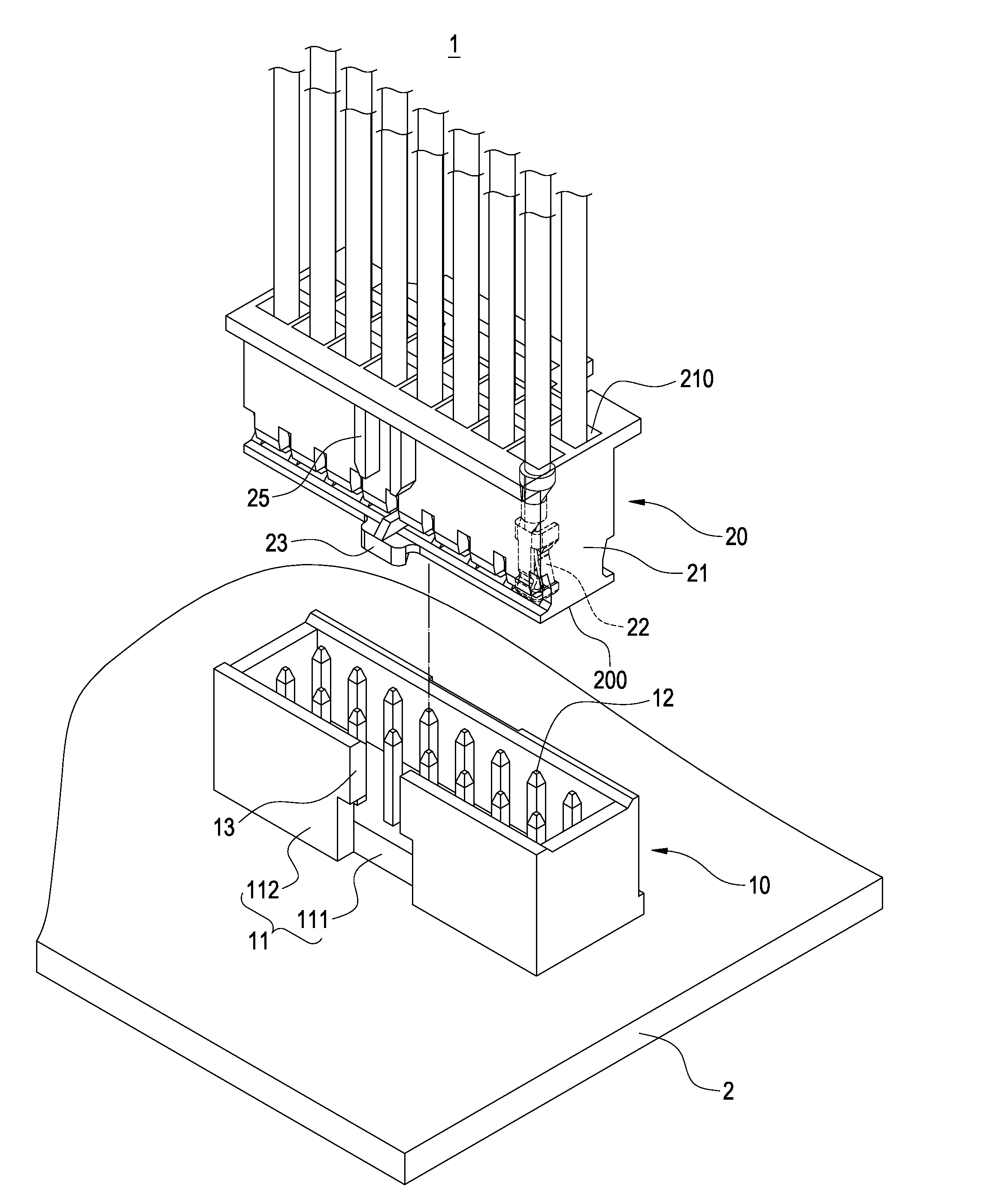
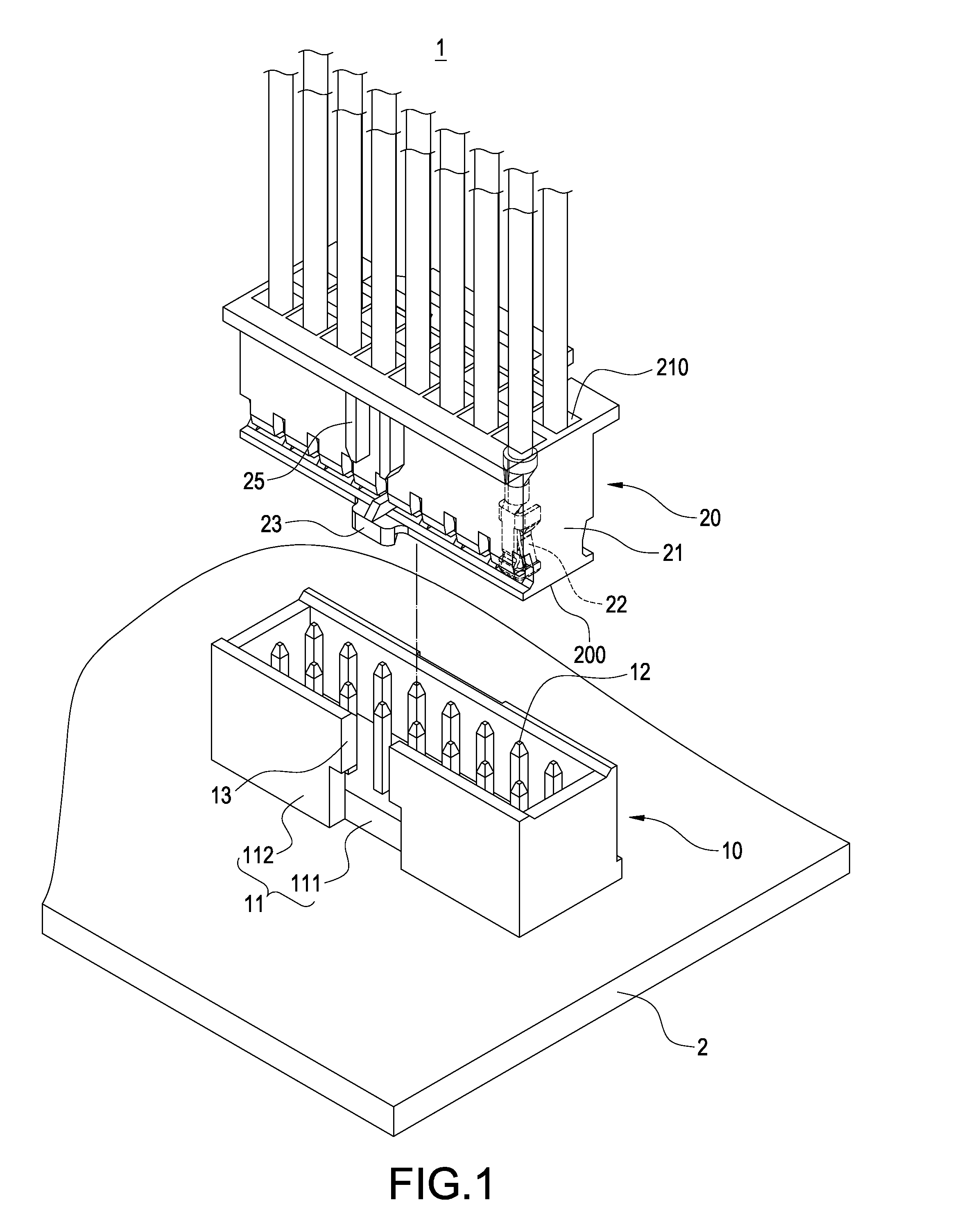
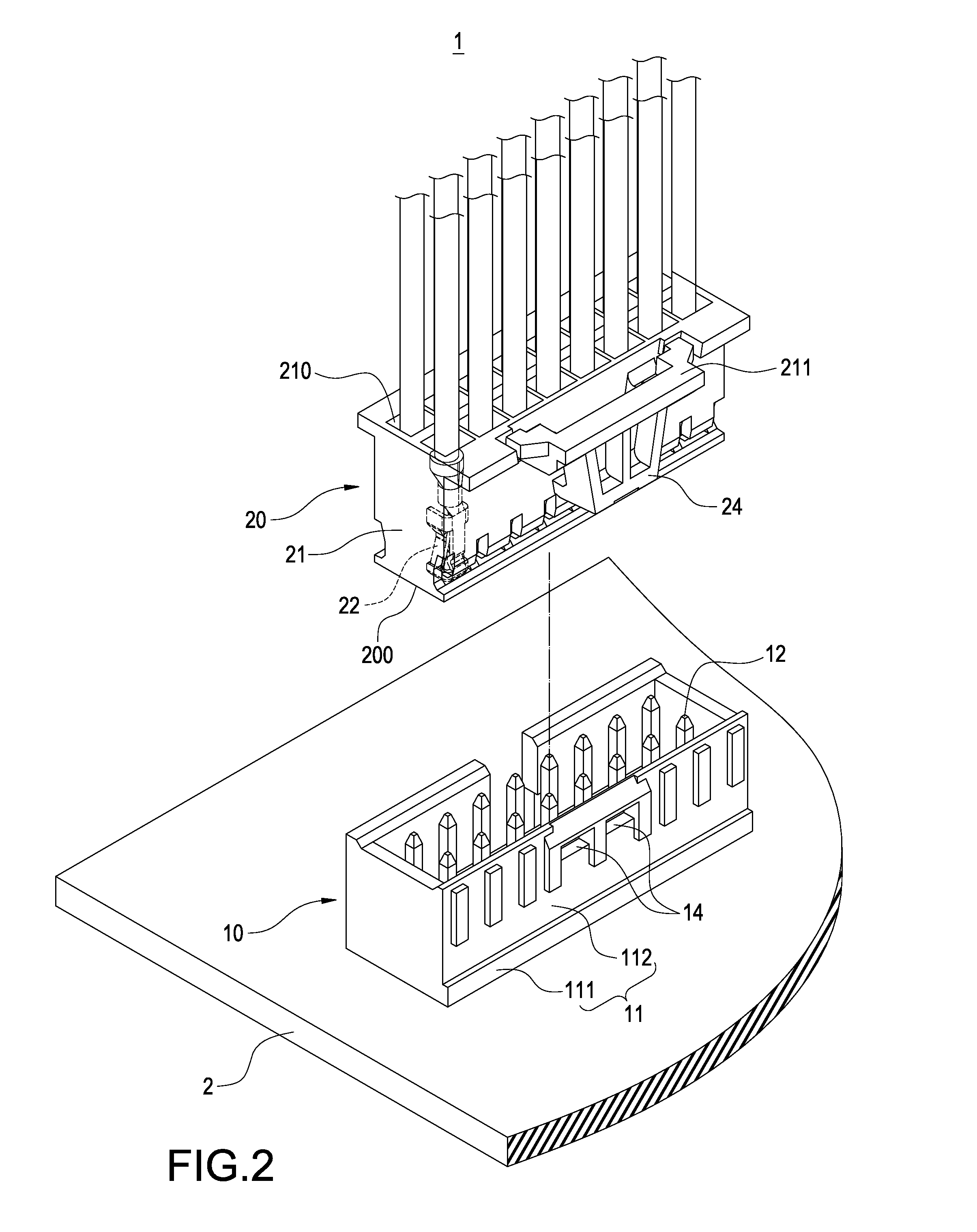
[0020]With reference to FIGS. 1 and 2 for schematic views of connecting a fool-proof electric connector of the present invention, the fool-proof electric connector 1 comprises a socket 10 and a plug 20.

[0021]The socket 10 includes a first insulating block 11, a plurality of first terminals 12 installed in the first insulating block 11, a positioning notch 13 formed on a lateral side of the first insulating block 11, and at least one positioning hole 14 formed at another opposite lateral side.

[0022]More specifically, in the structure of the socket 10, the first insulating block 11 includes a lower board 111 and a plurality of side panels 112 extended perpendicularly from the periphery of t...


PUM


Abstract

An electric connector includes a socket and a plug. The socket includes a first insulating block and a first terminal and the first insulating block has a positioning notch and a positioning hole. The plug includes a second insulating block and a second terminal, and the second insulating block has a plug end and a fool-proof block protruded from the plug end and extended towards the socket. The second insulating block includes a positioning hook arm formed on the other opposite side. When the second insulating block is plugged into the first insulating block, the fool-proof block is stopped at the positioning notch, and the positioning hook arm is latched into the positioning hole, such that the first terminals are electrically coupled to the second terminals, so as to assure a proper connection of the electric connectors and prevent damages caused by improper connection of the electric connectors.

Description

FIELD OF THE INVENTION[0001]The present invention generally relates to electric connectors, in particular to a fool-proof structure for connecting male and female connectors such as a plug and a socket.BACKGROUND OF THE INVENTION[0002]Traditionally, an electric connector cable is used for electrically coupling electronic products, and the electric connector cable is plugged into a port of an electronic product to transmit signals from the electronic product to another electronic product, so as to achieve the effect of connecting the electronic products.[0003]Present existing electric connector cables generally has an electric connector at one end and another electric connector at the other end for connecting ports of the electronic products, so that when the electric connector cable is plugged into the ports, both male and female electric connectors are plugged, and terminals of the male and female electric connectors are contacted with one another to achieve the electric connection...

Claims


Application Information

Patent Timeline
Patent Type & Authority Applications(United States)
IPC IPC(8): H01R24/28
CPCH01R13/6272H01R13/64H01R24/28
Inventor CHEN, KUAN-WUKUO, CHIA-HUNG
Owner BELLWETHER ELECTRONIC CORP
Learn More