
Inexpensive Treadmill with a Concave Platform

a treadmill and platform technology, applied in the field of treadmills, can solve the problems of increasing the cost of conventional treadmills including the middle roller, and increasing the cost of metal

Inactive Publication Date: 2012-10-25
DK CITY CORP
View PDF7 Cites 61 Cited by
  • Summary
  • Abstract
  • Description
  • Claims
  • Application Information

AI Technical Summary

Benefits of technology

[0009]It is the primary objective of the present invention to provide an inexpensive treadmill with a concave platform.

Problems solved by technology

The conventional treadmills including the middle rollers are expensive since metal is expensive and getting more expensive.

Method used


Image

  • Inexpensive Treadmill with a Concave Platform
  • Inexpensive Treadmill with a Concave Platform
  • Inexpensive Treadmill with a Concave Platform

Examples


Embodiment Construction

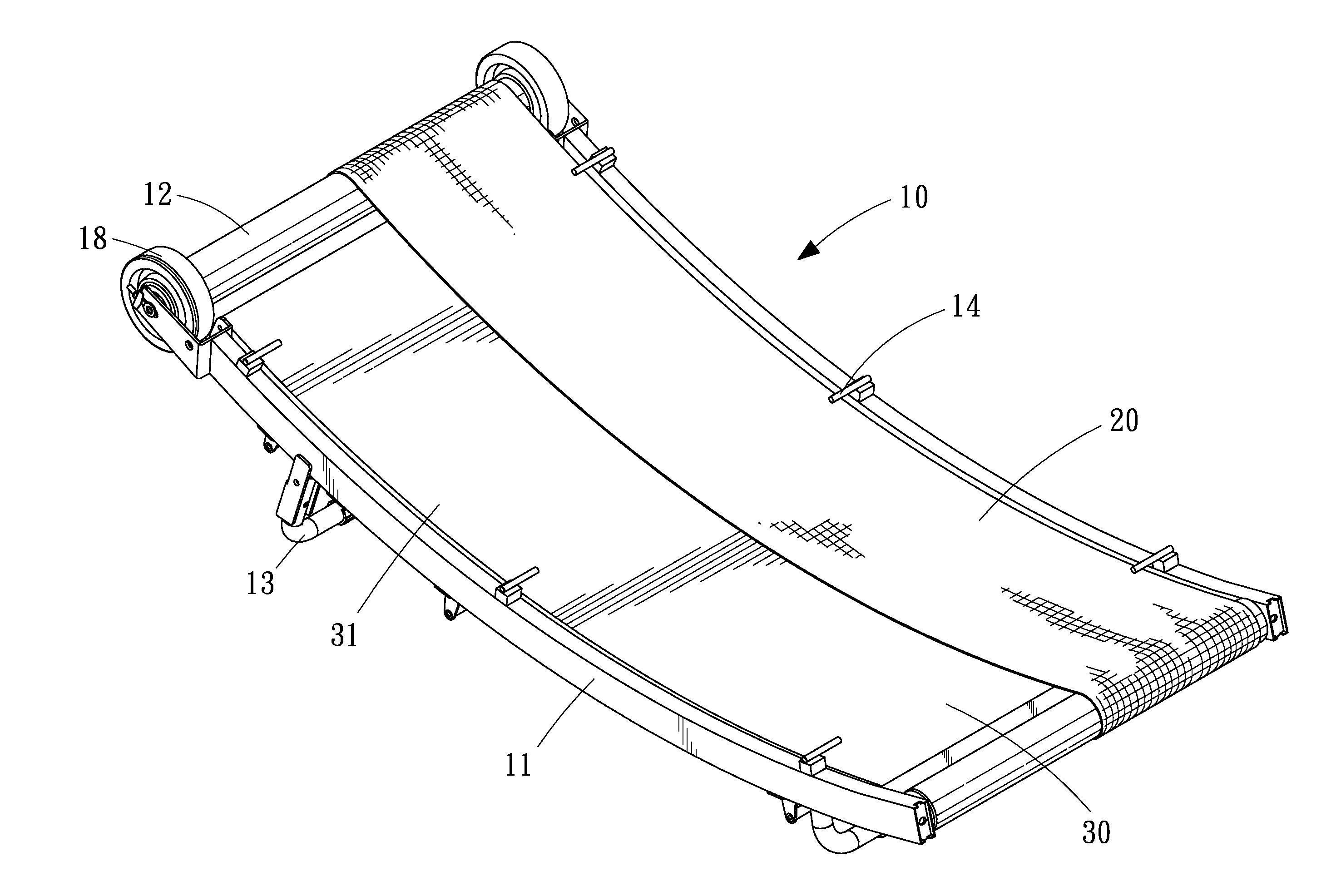
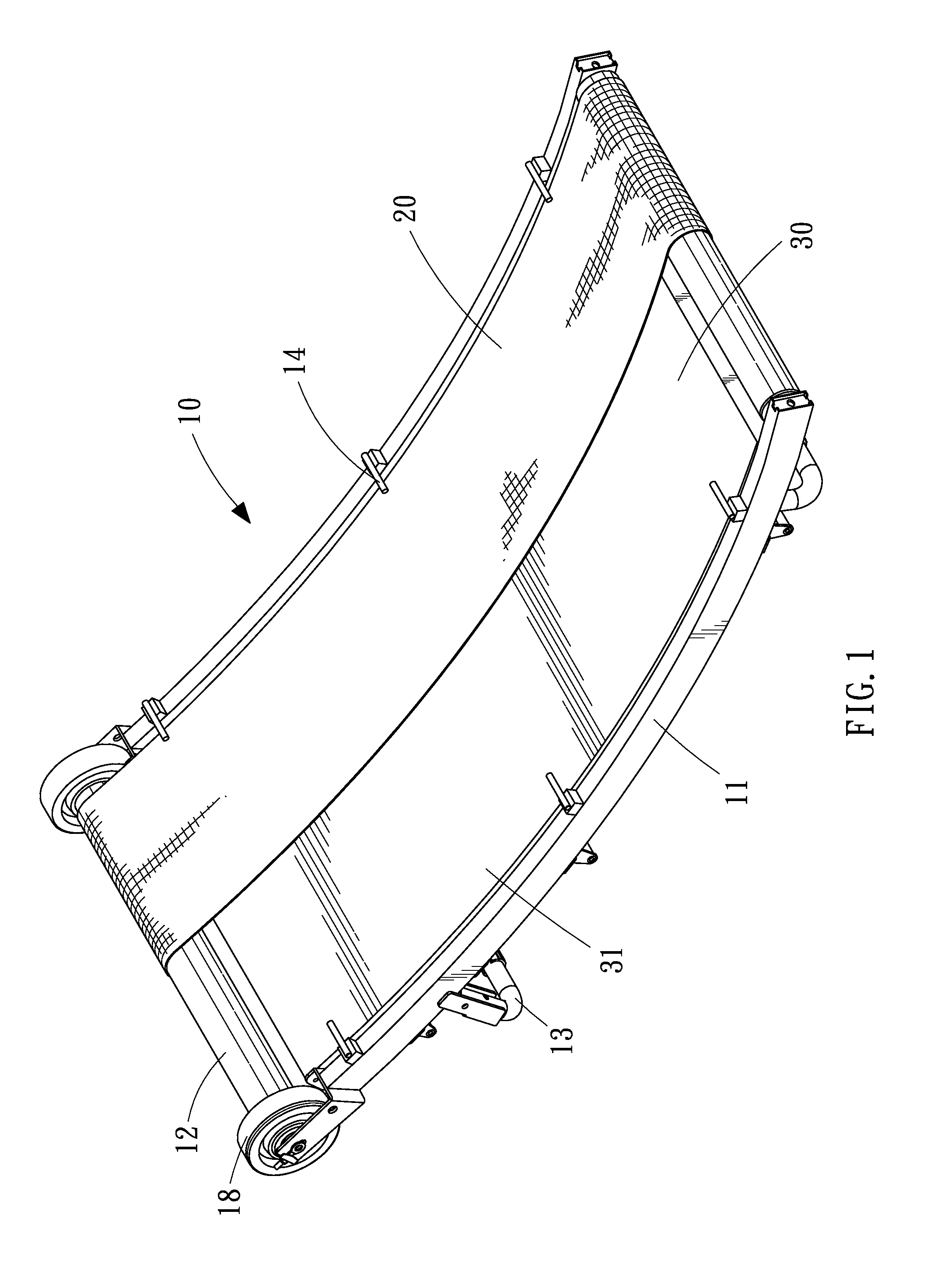
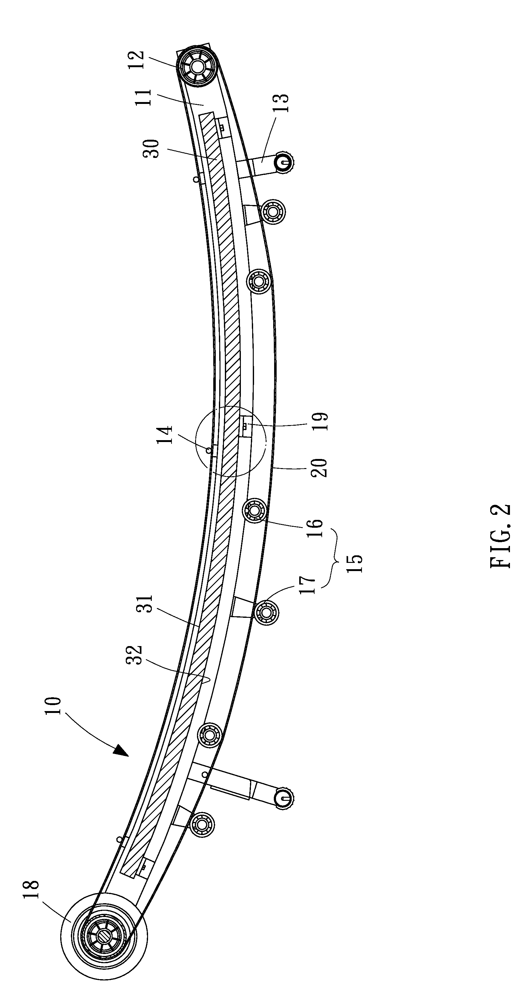
[0019]Referring to FIGS. 1 to 3, a treadmill includes a frame 10, two rollers 12, a concave platform 30, a belt 20, upper guiding units, and lower guiding units 15 according to a first embodiment of the present invention. The frame 10 includes two lateral members 11. The lateral members 11 of the frame 10 are preferably concave tubes. A wheel 18 is supported on a bracket secured to a front end of each of the lateral members 11 of the frame 10. The wheels 18 are used for rolling on the ground or a floor for transporting the treadmill.

[0020]Two supporting elements 13 are connected to the frame 10. Each of the supporting elements 13 includes a horizontal section extending between two vertical sections each connected to a related one of the lateral members 11 of the frame 10. The horizontal sections of the supporting elements 13 are used for contact with the ground or floor for positioning the treadmill.

[0021]The rollers 12 are supported on the lateral members 11 of the frame 10. Each o...


PUM


Abstract

A treadmill includes a frame, two rollers, a platform and a belt. The rollers are supported on the frame. The platform is supported on the frame and formed with a concave upper face. The belt is wound around the rollers and formed with a lower section and an upper section supported on the concave upper face of the concave platform.

Description

BACKGROUND OF INVENTION[0001]1. Field of Invention[0002]The present invention relates to a treadmill and, more particularly, to an inexpensive treadmill including a concave platform.[0003]2. Related Prior Art[0004]A conventional treadmill includes a frame, two rollers, a planar platform and a belt. The frame includes two lateral members in the form of rectilinear tubes corresponding to the planar platform. The rollers are supported on the lateral members of the frame. The planar platform is also supported on the lateral members of the frame between the rollers. The belt is wound around the rollers and formed with an upper section supported on the planar platform.[0005]There has been devised another conventional treadmill including a frame, front and rear rollers, middle rollers and a belt. The frame includes two rectilinear lateral members. The front, rear and middle rollers are supported on the rectilinear lateral members of the frame. The belt is wound around the front and rear ro...

Claims


Application Information

Patent Timeline
IPC IPC(8): A63B22/02
CPCA63B22/0285A63B22/02
Inventor LO, CHIU HSIANG
Owner DK CITY CORP
Learn More