
Developing device and image forming apparatus

a technology of developing device and image forming apparatus, which is applied in the direction of electrographic process apparatus, instruments, optics, etc., can solve the problems of easy depletion of developer, unnecessarily increasing developer amount, and reducing the carrier that stays in the developing devi

Active Publication Date: 2012-07-26
KONICA MINOLTA BUSINESS TECH INC
View PDF4 Cites 20 Cited by
  • Summary
  • Abstract
  • Description
  • Claims
  • Application Information

AI Technical Summary

Benefits of technology

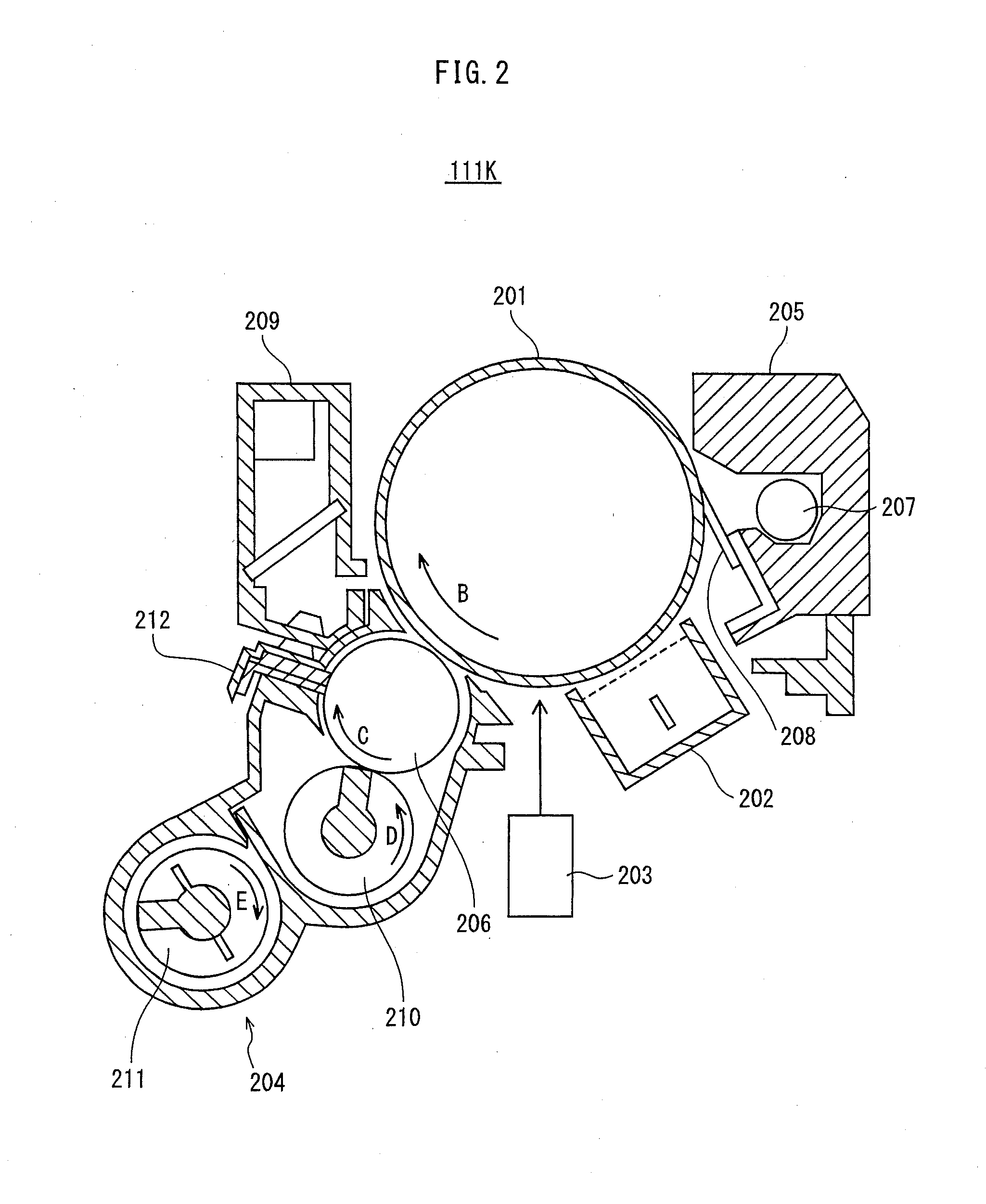
[0014]The present invention has been achieved in view of the above problem, and a developing device pertaining to the present invention A trickle-type developing device that receives supply of two-component developer including toner, supplies the toner to a photoreceptor, and develops an electrostatic latent image formed on the photoreceptor, the developing device comprising: a stirring and conveying tank provided with stirring and conveying screws that stir, convey and circulate the developer; a hollow cylindrical discharge member via which a part of the developer is conveyed from the stirring and conveying tank to a discharge opening through which the part of the developer is discharged from the discharge member, the discharge opening being provided in the discharge member; and a reverse flow generating screw provided inside a portion of the discharge member, sharing one of rotation shafts of the stirring and conveying screws, and pushing back a part of the developer in a direction from the discharge opening toward the stirring and conveying tank, wherein the portion has a reduced-radius part and in a cross section thereof perpendicular to an axial direction of the one of rotation shafts of the stirring and conveying screws, an inner radius of the portion is smaller in the reduced-radius part than in the remaining part of the portion, the reduced-radius part being located in a lower part of the portion with respect to a vertical direction of the portion.

Problems solved by technology

However, carrier that stays in a developing device degrades over time.
However, the surface overflow type developing devices have a problem in that an amount of discharged developer easily varies by being influenced by inclination of the developing device in an axial direction of the shafts thereof.
That is, when the developing device is inclined so that the height of one end thereof discharging the developer is low, the amount of discharged developer unnecessarily increases, and as a result, carrier that has not particularly degraded is discarded.
To the contrary, when the developing device is inclined in the opposite direction, the amount of discharged carrier becomes insufficient, and as a result, degraded carrier stays in the developing device.
However, as the stirring and conveying speed increases, developer that is conveyed jumps the downflow openings more easily due to inertia forces.
As a result, it becomes difficult to stabilize the amount of discharged developer.
Such a problem of instability becomes especially evident when a system speed exceeds 200 mm / second.

Method used


Image

  • Developing device and image forming apparatus
  • Developing device and image forming apparatus
  • Developing device and image forming apparatus

Examples


Embodiment Construction

[0028]An embodiment of a developing device and an image forming apparatus pertaining to the present invention is described below with reference to the drawings.

[1] STRUCTURE OF IMAGE FORMING APPARATUS

[0029]First, a structure of an image forming apparatus pertaining to the present embodiment is described below.

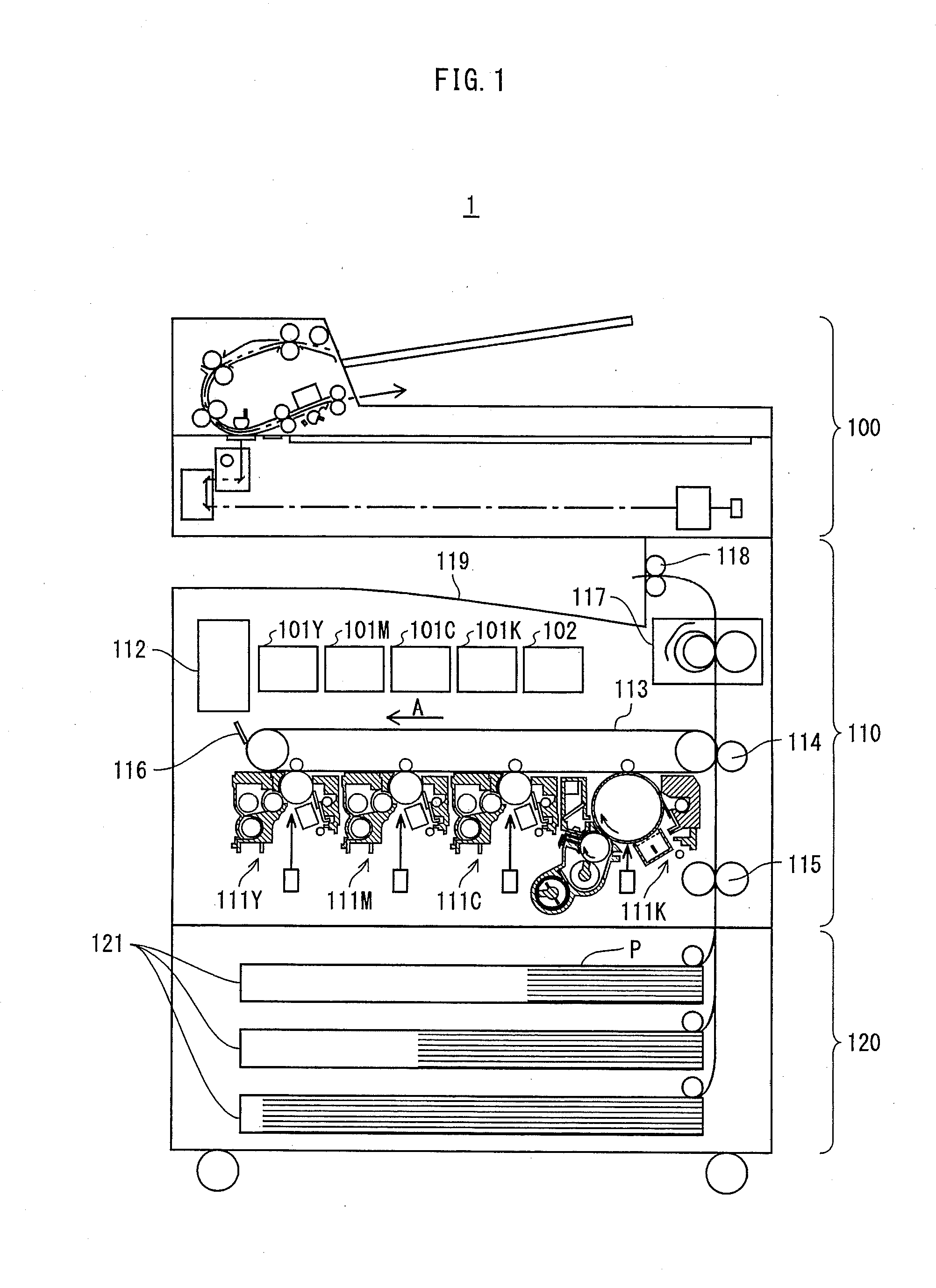
[0030]FIG. 1 shows a main structure of the image forming apparatus pertaining to the present embodiment. As shown in FIG. 1, an image forming apparatus 1 includes a document reader 100, an image forming unit 110, and a paper feeder 120. The document reader 100 forms image data by optically reading a document through an Automatic Document Feeder (ADF) taking a document placed on a document tray. The formed image data is stored in a controller 112 described later.

[0031]The image forming unit 110 includes imaging units 111Y-111K, the controller 112, an intermediate transfer belt 113, a secondary transfer roller pair 114, a timing roller pair 115, a cleaner 116, a fixing device 117...


PUM


Abstract

A trickle-type developing device comprising: a stirring and conveying tank provided with stirring and conveying screws that circulate the developer; a discharge member via which a part of the developer is conveyed from the tank to a discharge opening through which the developer is discharged, the discharge opening being provided in the discharge member; and a reverse flow generating screw provided inside a portion of the discharge member, sharing one of rotation shafts of the stirring and conveying screws, and pushing back a part of the developer, wherein the portion has a reduced-radius part and in a cross section thereof perpendicular to an axial direction of the one of rotation shafts, an inner radius of the portion is smaller in the reduced-radius part than in the remaining part, the reduced-radius part being located in a lower part of the portion with respect to a vertical direction of the portion.

Description

CROSS-REFERENCE TO RELATED APPLICATIONS[0001]This application is based on an application No. 2011-9498 filed in Japan, the contents of which are hereby incorporated by reference.BACKGROUND OF THE INVENTION[0002](1) Field of the Invention[0003]The present invention is related to a developing device and an image forming apparatus, and in particular to a technology for keeping an amount of developer constant in a trickle-type developing device regardless of a change in a system speed.[0004](2) Description of the Related Art[0005]In an image forming apparatus using two-component developer, which includes toner and carrier, when toner is consumed in image formation, fresh toner is supplied as required. However, carrier that stays in a developing device degrades over time. In order to lengthen the lifespan of the developing device, despite the degradation of carrier, a trickle-type developing device has been proposed. The trickle-type developing device supplies fresh carrier while discard...

Claims


Application Information

Patent Timeline
Patent Type & Authority Applications(United States)
IPC IPC(8): G03G15/08
CPCG03G15/0189G03G2215/0132G03G15/0893
Inventor OKUNO, YUUSUKEWATANABE, WATARU
Owner KONICA MINOLTA BUSINESS TECH INC
Learn More