
Wall mounting bath accessory assembly

a bath and accessory technology, applied in the direction of washstands, scaffold accessories, lighting supports, etc., can solve the problems of difficult removal and easy disengagement of the base from the wall

Inactive Publication Date: 2012-05-17
GLOBE UNION INDAL
View PDF8 Cites 13 Cited by
  • Summary
  • Abstract
  • Description
  • Claims
  • Application Information

AI Technical Summary

Benefits of technology

[0008]The primary object of the present invention is to provide a wall mounting bath accessory assembly which is capable of overcoming the shortcomings of the conventional wall mounting bath accessory assembly.
[0009]Further object of the present invention is to provide a wall mounting bath accessory assembly that when the retaining member is touched to act accidentally, it is stopped to fall from the fixing member, obtaining a safe purpose.
[0010]Also a further object of the present invention is to provide a wall mounting bath accessory assembly that when disassembling the retaining member, the two second hooks of the retaining member are moved outward to disengage from the engaging portion of the fixing member, and then the second hooks are pushed upward so that the first hook disengages from the first chamber of the fixing member to remove the retaining member, the covering, and the shaft, thus preventing the bath accessory assembly from being removed easily, achieving a theft-proof purpose.
[0011]Another object of the present invention is to provide a wall mounting bath accessory assembly that the related components, such as the retaining member, the covering member, and the shaft, are assembled together without using any screw bolts, having a quick assembly and disassembly.

Problems solved by technology

The fixing member is locked to a wall by using an anchor and a first bolt element, and includes a peripheral surface to be covered by a disc-shaped cover on the base, and a second bolt elements is inserted through the cover to retain the base to the fixing member, however, such the base disengages from the wall easily and is removed difficultly.

Method used


Image

  • Wall mounting bath accessory assembly
  • Wall mounting bath accessory assembly
  • Wall mounting bath accessory assembly

Examples


Embodiment Construction

[0032]The present invention will be clearer from the following description when viewed together with the accompanying drawings, which show, for purpose of illustrations only, the preferred embodiment in accordance with the present invention.

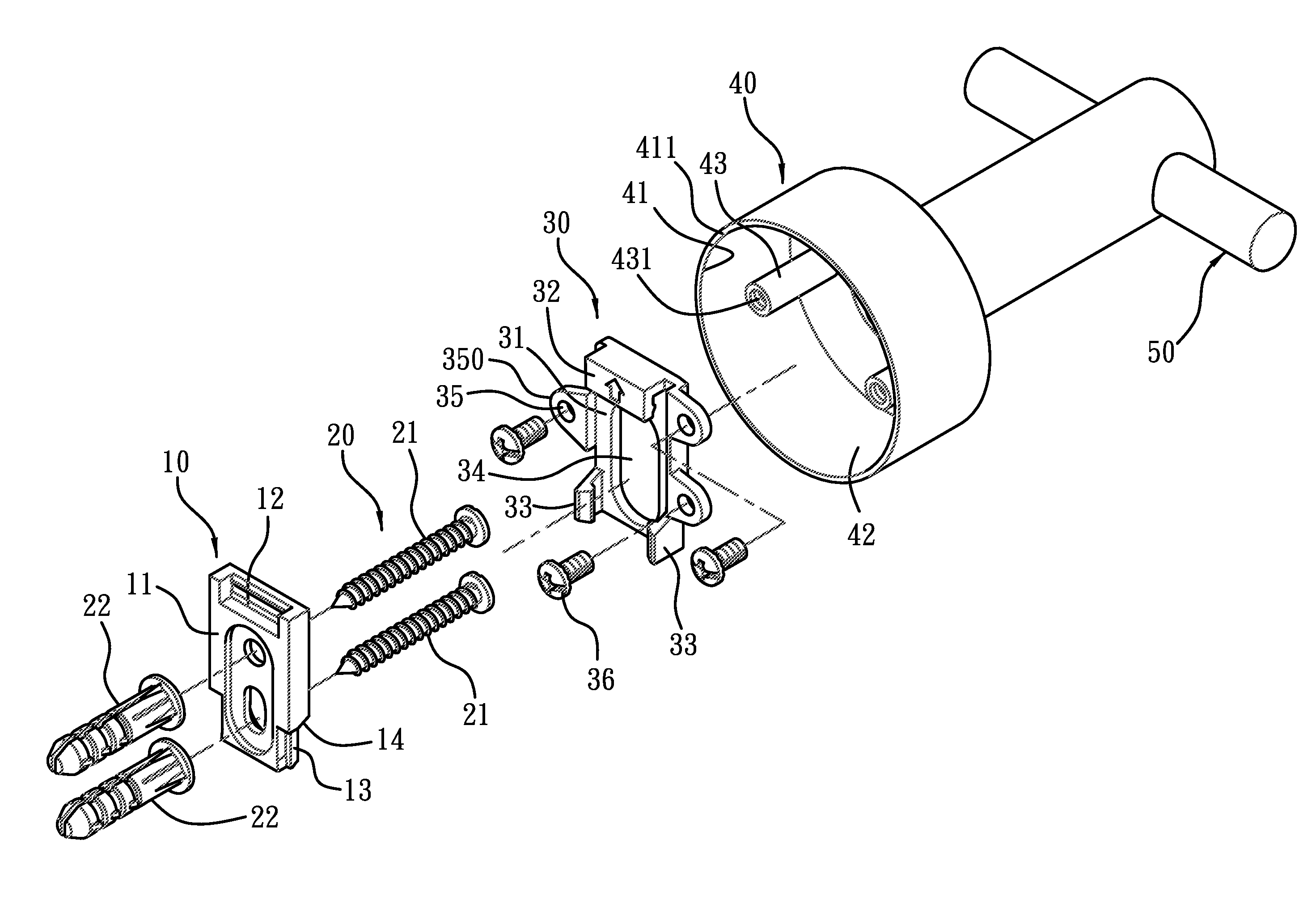
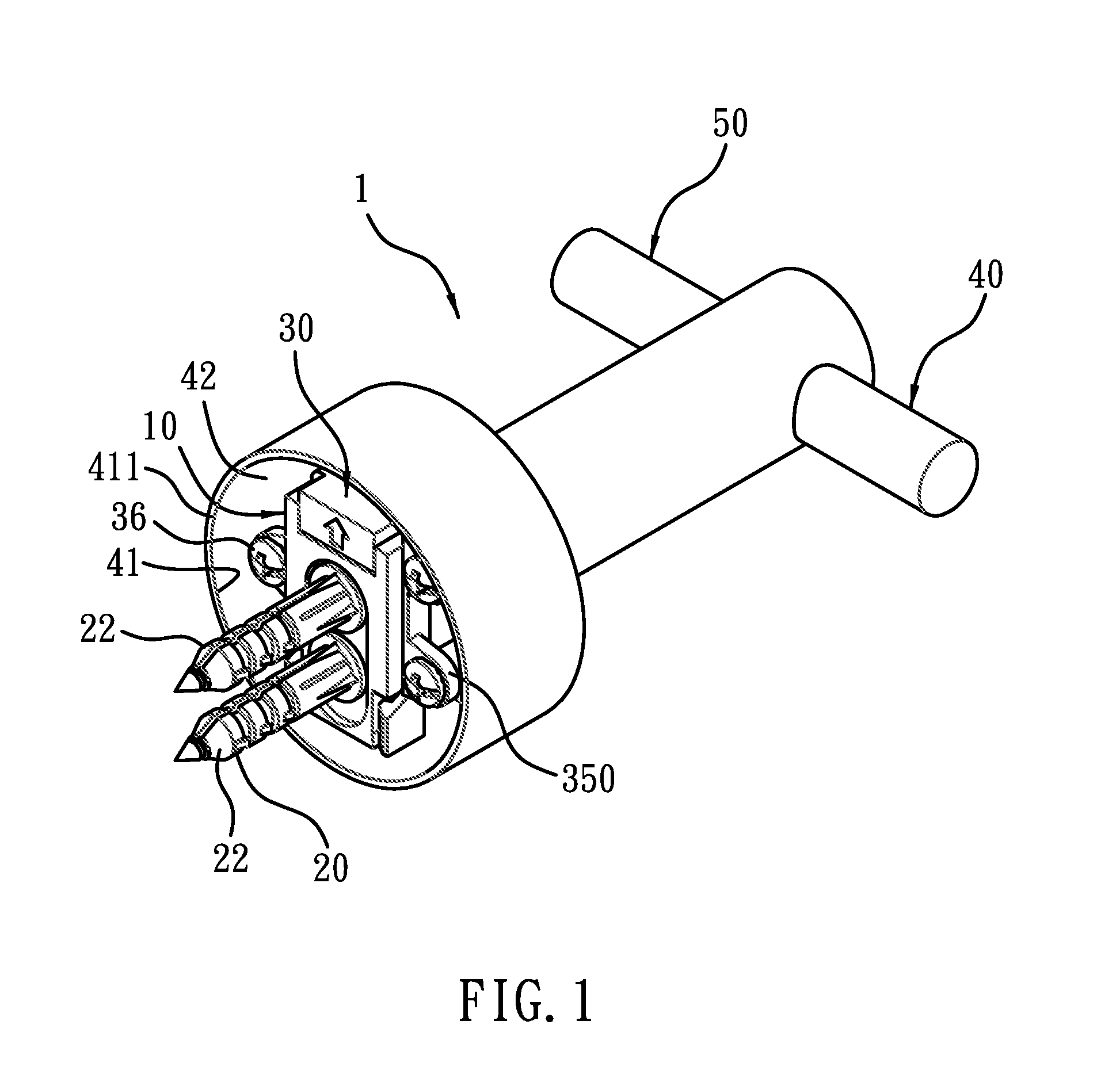
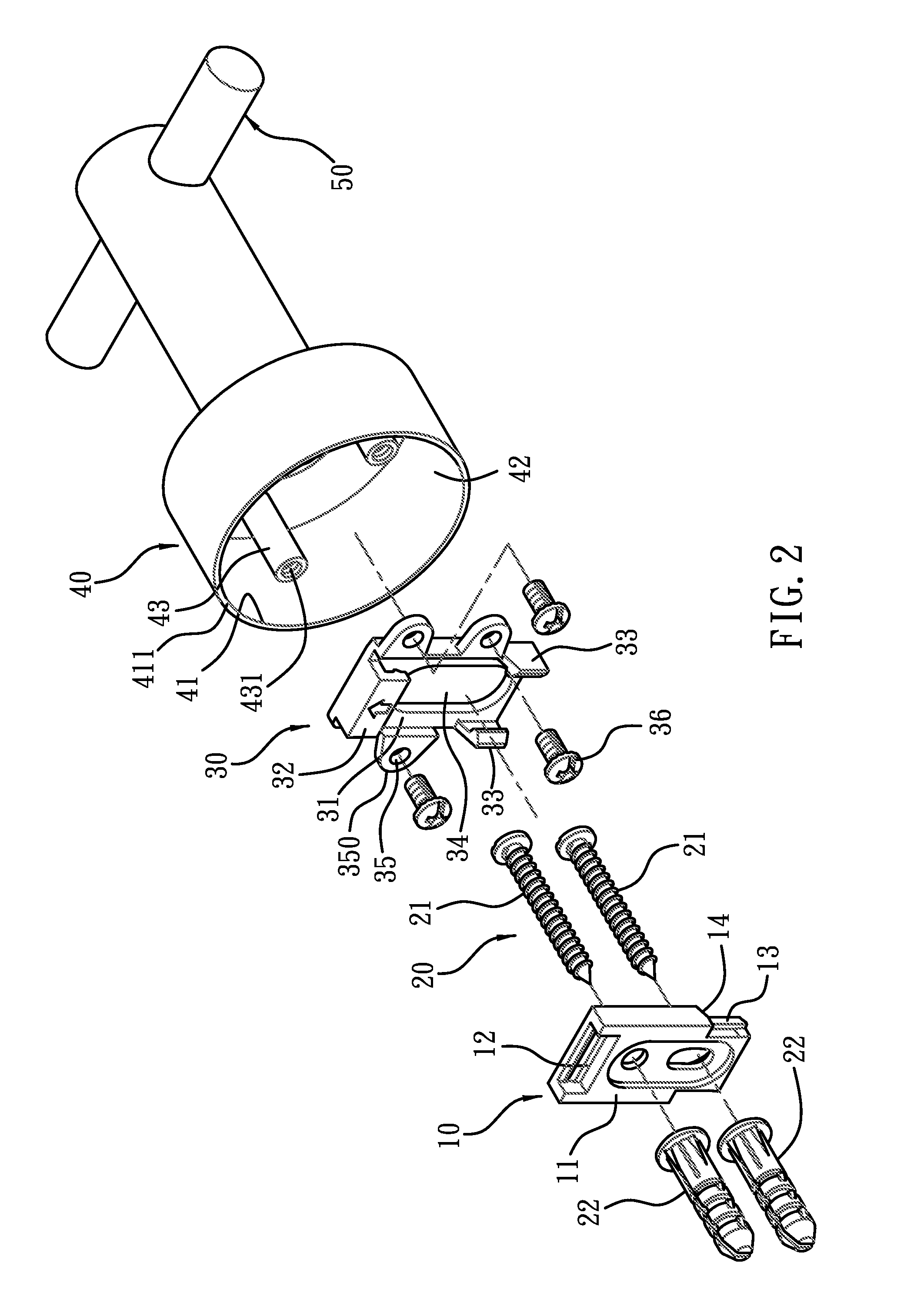
[0033]Referring to FIGS. 1 and 2, a wall mounting bath accessory assembly 1 according to a first embodiment of the present invention comprises a fixing member 10, a locking device 20, a retaining member 30, a covering member 40, and a shaft 50.

[0034]The fixing member 10, as shown in FIGS. 3-6, includes a contacting fence 11 disposed on an inner side thereof to be fixed onto an outer face 2a of a wall 2 as illustrated in FIG. 7A; the contacting fence 11 includes a recess 12 fixed on an upper end thereof, and between the recess 12 and the outer face 2a of the wall 2 is defined a first chamber 120, the first chamber 120 includes an opening 121 formed on a top end thereof; the fixing member 10 includes two engaging portions 13 extending from two side...


PUM


Abstract

A wall mounting bath accessory assembly contains a fixing member including a contacting fence with a recess and two engaging portions, and the engaging portion including a shoulder arranged on an upper end thereof; a retaining member including a body, an first hook, and two second hooks; the first hooks being inserted through an upper end of the fixing member to retain with the recess so as to limit the retaining member; the second hook including a hooking segment to retain with the first hook and the recess, and when a lower end of the retaining member is pushed inward, the engaging portions of the fixing member abutting against the retaining member to cause a resilient deformation so that the retaining member retains with the engaging portions, and a top end of the anchor being stopped by the shoulder so that an upward displacement of the retaining member is limited.

Description

BACKGROUND OF THE INVENTION[0001]1. Field of the Invention[0002]The present invention relates to a wall mounting bath accessory assembly to be fixed on a wall.[0003]2. Description of the Prior Art[0004]A conventional wall mounting bath accessory assembly is used in a rack to hold cloth, cap, towel and toilet papers, and includes a fixing member and a base. The fixing member is locked to a wall by using an anchor and a first bolt element, and includes a peripheral surface to be covered by a disc-shaped cover on the base, and a second bolt elements is inserted through the cover to retain the base to the fixing member, however, such the base disengages from the wall easily and is removed difficultly.[0005]To overcome above-mentioned shortcomings, an improved wall mounting bath accessory assembly is disclosed in CN Pat. Nos. 201365798 and 2601614, and US Pub. No. US 20090108157 that include a retaining member to be locked to the base in advance so that the base is fixed by using the ret...

Claims


Application Information

Patent Timeline
IPC IPC(8): F16M13/02
CPCA47K2201/025A47K10/10
Inventor HSU, WEIMIENNAN, FENYONGLI, CHUNHUNG
Owner GLOBE UNION INDAL
Learn More