
Method and wideband antenna system to minimise the influence of interference sources

a wideband antenna and interference source technology, applied in the field of wideband antenna systems to minimise the influence of interference sources, can solve the problems of limiting and affecting the actual function of the electronic system

Active Publication Date: 2012-05-10
SAAB AB
View PDF3 Cites 12 Cited by
  • Summary
  • Abstract
  • Description
  • Claims
  • Application Information

AI Technical Summary

Benefits of technology

The invention provides a method and system for reducing interference in a wideband antenna system. The method involves controlling the signal-to-noise ratio (SNR) of the antenna system by optimizing the SNR of the antenna elements and sub arrays connected to the electronic system. This is done by using an optimization process over the instantaneous bandwidth of the antenna system. The system also includes a transforming means to affect the waveforms between the antenna elements and the electronic system, which cancels out interfering frequencies. The invention also provides an interference source parameter estimation method and a JRC module for performing the evaluation and outputting the results. The technical effects of the invention include improved SNR, reduced interference, and improved estimation of interference source parameters.

Problems solved by technology

Both alternatives limit the time available for the actual function of the electronic system as both solutions will occupy the antenna aperture of the electronic system during operation.
Side lobes are difficult to avoid when designing antennas and jammer signals can be picked up by these side lobes.
As the jammer signals are often powerful they will cause interference with the signal from a target picked up in the main lobe even if the reception sensitivity of the side lobe is much below the reception sensitivity of the main lobe.
The drawback with the existing SLC solutions of today is that only narrow band cancellation of the side lobe is possible.
This is a serious problem as radar antennas are often operating over a very wide bandwidth while side lobe cancellation is only effective in a part of the operating bandwidth of the radar antenna.

Method used


Image

  • Method and wideband antenna system to minimise the influence of interference sources
  • Method and wideband antenna system to minimise the influence of interference sources
  • Method and wideband antenna system to minimise the influence of interference sources

Examples


Embodiment Construction

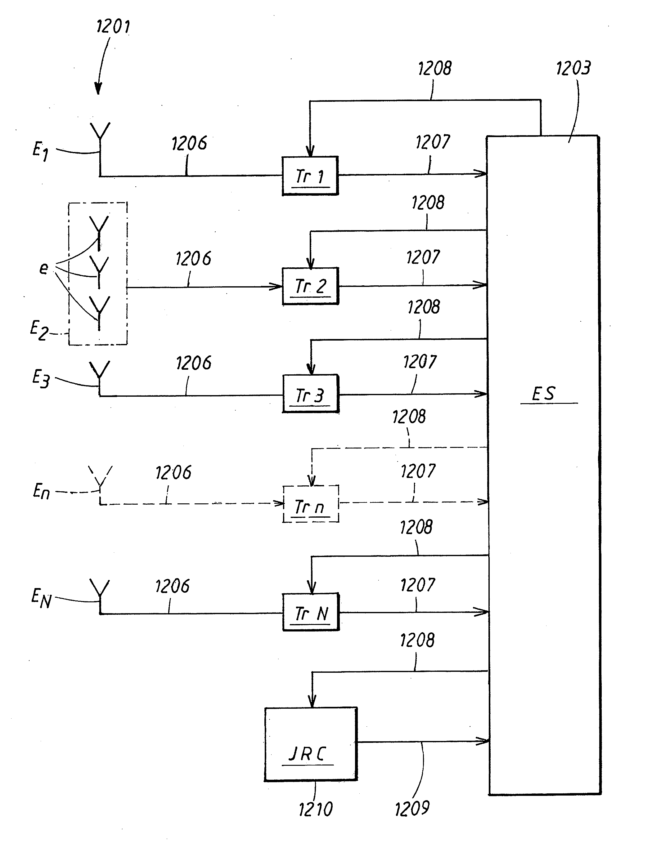
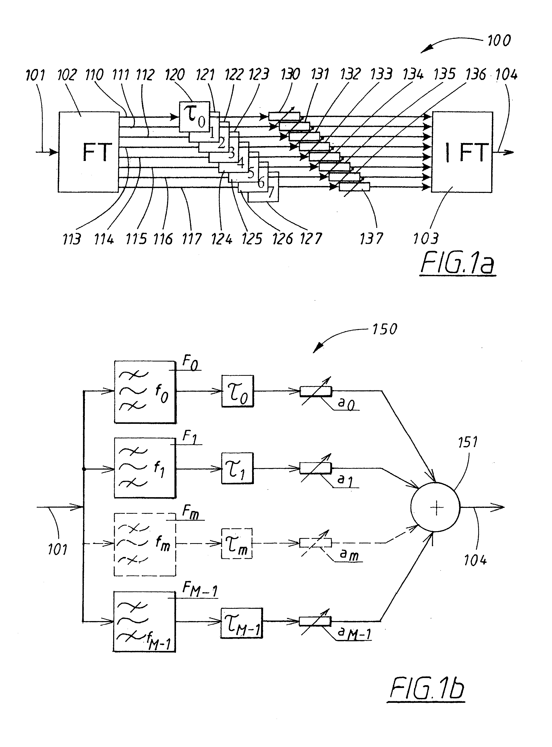
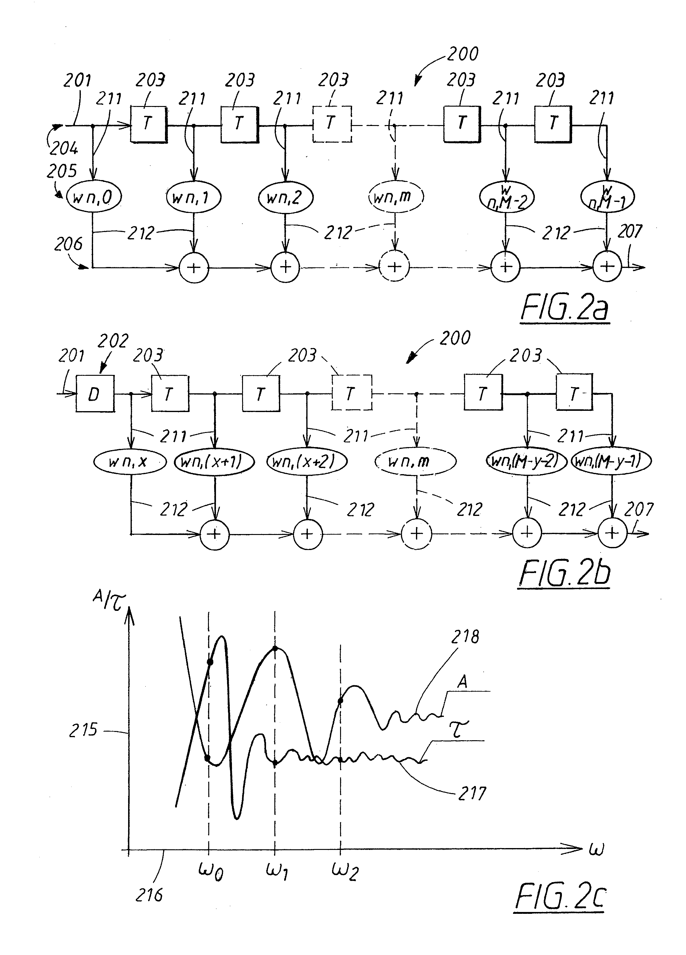
[0041]The invention will now be described in detail with reference to the enclosed drawings.

[0042]Henceforth in the description the invention will be exemplified with a radar system as the electronic system which is subject to interference from a jammer, characterized as an intentional interference. The interference can also be caused by an unintentional Radio Frequency Interference (RFI) or clutter picked up in side lobes to the radar antenna and comprising signals reflected from objects within the radar antenna coverage. Henceforth in the description the interference will be exemplified by a jammer unless otherwise stated.

[0043]The information needed for estimation of the interference parameters are obtained from transforming means or from the electronic system as will be explained.

[0044]An antenna pattern is defined as radiated power as a function of direction when the antenna is operated in transmit mode and as sensitivity as a function of directions when the antenna is operated...


PUM


Abstract

A method to minimize influence of interference sources by control of a signal to noise / interference ratio of a wideband antenna system connected to an electronic system. The wideband antenna system includes at least one array of at least two antenna elements / sub arrays. The signal to noise / interference ratio control includes establishing of cancellation directions for interfering frequencies in the antenna pattern in the direction of interference sources. The wideband antenna system is operational over a system bandwidth and operates with an instantaneous bandwidth. Estimation of interference source parameters is performed in an evaluation process. A wideband antenna system implementing the method.

Description

TECHNICAL FIELD[0001]The invention relates to the field of interference on electronic systems such as jammer interference on radar systems.BACKGROUND ART[0002]It is often desirable to minimize the influence of interference sources and also to estimate characteristic parameters of interference sources disturbing an electronic system, such as jammers or unintentional Radio Frequency Interference (RFI) disturbing a radar or a communications system. Today a separate Side Lobe Cancelling system (SLC) is used to minimize the interference from interference sources and a separate ESM (Electronic Support Measurement) receiver is today normally used to estimate interference parameters from the interference sources. The ESM system is also used for other purposes. An alternative is that this function of estimating interference parameters is performed by the electronic system. Both alternatives limit the time available for the actual function of the electronic system as both solutions will occup...

Claims


Application Information

Patent Timeline
Patent Type & Authority Applications(United States)
IPC IPC(8): H04B1/10
CPCG01S7/023H01Q3/2617G01S2013/0245G01S7/36G01S7/0236
Inventor FALK, KENT
Owner SAAB AB
Learn More