
Immunoassay product and process

a technology of immunoassay and product, applied in the field of immunoassay product and process, can solve the problems of large scope of biological effort, long process, high noise and low detection level

Active Publication Date: 2011-10-20
EMD MILLIPORE CORP
View PDF3 Cites 55 Cited by
  • Summary
  • Abstract
  • Description
  • Claims
  • Application Information

AI Technical Summary

Benefits of technology

In another embodiment a rapid, efficient and convenient method to detect one or more biological entities on a blotting membrane is provided. The detection can relate to the position, nature or amount of the biological substance on a membrane. The invention method involves a pressure assisted regiment, selected from positive pressure or a vacuum for the supply and removal of reagents to and from the blotting membrane and permits washing of the contaminants from substances embedded in the membrane that are to be detected using very low volumes of liquid and reagents. This method enables completion of the blocking, washing and antibody binding steps in about 30-45 minutes without compromising blot quality. One simply takes a holder, opens it and places the blotting membrane(s) on one of the surfaces such that the lower surface of the blotting membrane is adjacent the porous support and the upper surface of the blotting membrane is adjacent the flow distributor when the device is closed around the membrane(s). The device is placed on or in a manifold having a pressure or vacuum supply and the process is commenced.

Problems solved by technology

Nonbiological materials can also be separated using gels or other chromatographic supports as well, but the scope of effort with regard to biologicals is greater.
The “spots” are then detected, at a minimum, by blocking the membrane with a protein or detergent solution to reduce non-specific binding (which otherwise leads to a high level of noise and low level of detection).
It is a lengthy process that most researchers dislike and which consumes (wastes) a large volume of reagents.
The system requires large volumes of liquid in order to operate, is cumbersome to employ and is still quite time consuming.
However, they discount this effort as it is only available in small volume applications and still is uncontrollable.

Method used


Image

  • Immunoassay product and process
  • Immunoassay product and process
  • Immunoassay product and process

Examples


Embodiment Construction

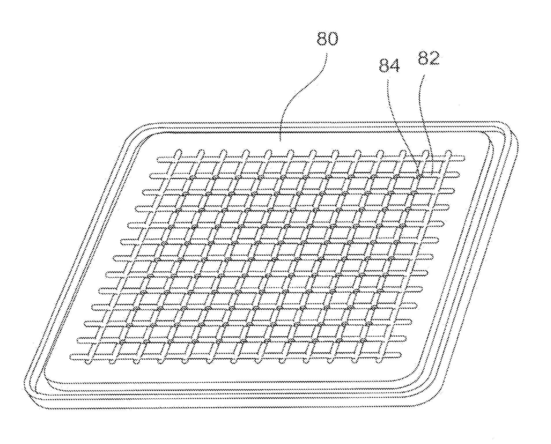
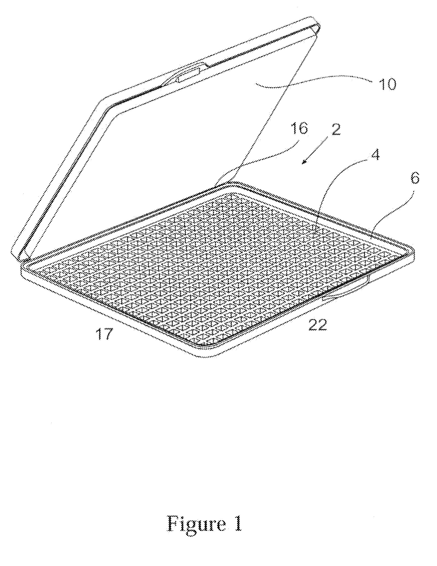
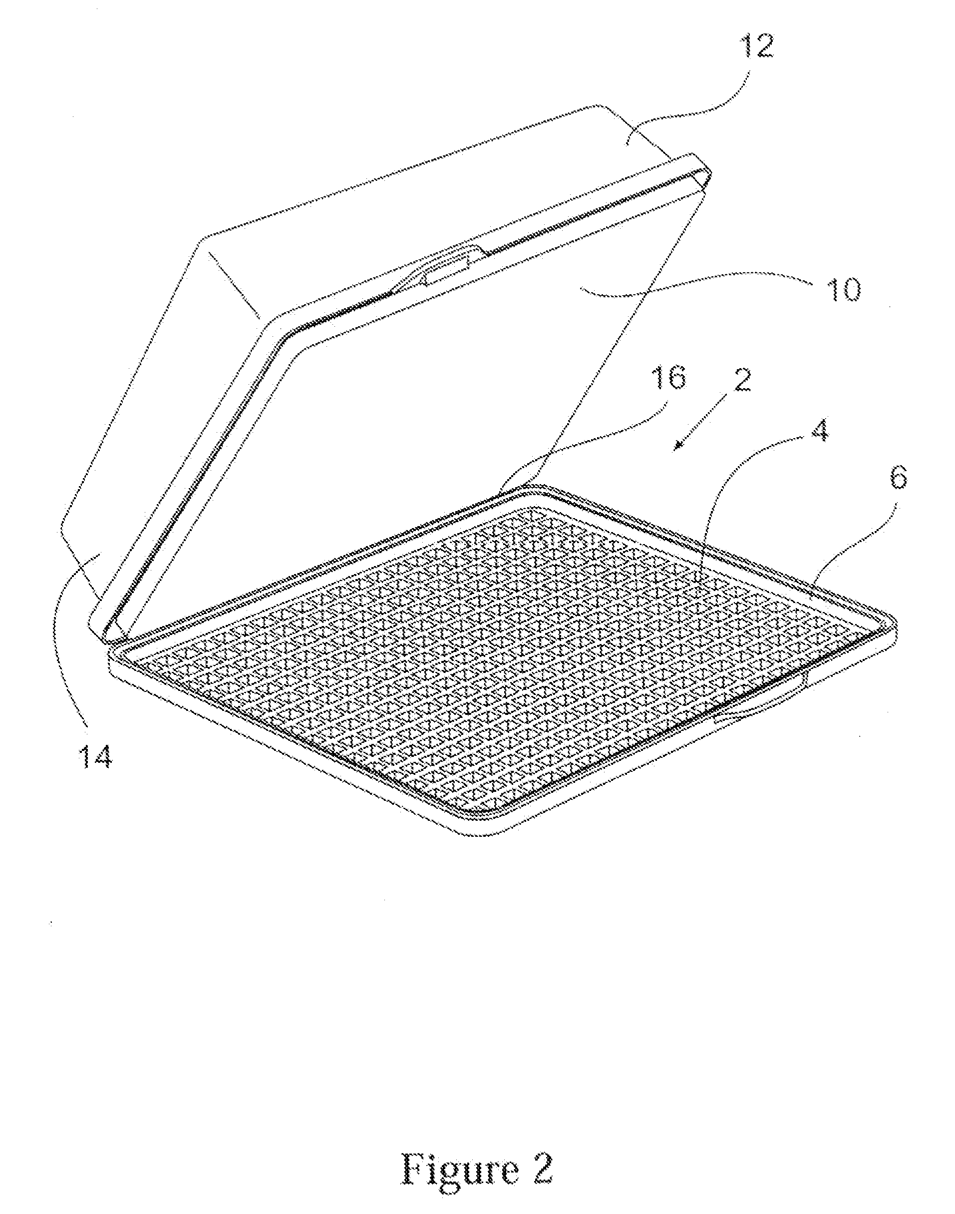
As shown in FIG. 1, the holder 2 is comprised of two portions. The first or lower portion is a porous support 4. Preferably the support is formed with an edge 6 or mounting piece that is designed to fit into or onto a manifold 8 (FIG. 3). One or more layers of a blotting membrane (not shown) are placed on top of the support 4 such that the bottom surface of the membrane(s) is in contact with the support's upper surface. The second portion of the holder 2 is a porous flow distributor 10 that is applied against the top of the blotting membrane(s) (not shown).

The top 10 and the bottom 4 pieces are preferably attached to each other at least during use to hold the one or more membranes securely in place. As shown in FIGS. 1 and 2 the two portions 4 and 10 of the holder 2 are held together by a hinge 16. As shown in this embodiment the hinge is a “live” hinge that bonds the two portions together. Alternatively, the hinge could be made separately and attached using adhesives, heat bonds or...


PUM


Abstract

The invention is directed to an apparatus useful in conducting detection of compounds on blotting membranes. The device is comprised of several layers including a porous support layer below the blotting membrane(s), a flow distributor above the blotting membrane(s) and optionally a well on the flow distributor to contain the liquid to the desired area and to allow for lower starting volumes of such liquid. Preferably, the flow distributor is a non-binding or low binding hydrophilic porous membrane such as a 0.22 micron membrane and the support layer is a grid or sintered porous material. The distributor and support are held together to form an envelope around the membrane(s). The use of a hinge, clips and other such devices is preferred in doing so.

Description

BACKGROUND OF THE INVENTIONThe use of gel electrophoresis is currently the ubiquitous technique for the separation of biological materials. Nonbiological materials can also be separated using gels or other chromatographic supports as well, but the scope of effort with regard to biologicals is greater. Typical applications include separation of nucleic acid fragments of various sizes either in the context of sequence determination; in the detection of polymorphisms; or verification of sizes in other contexts. Also frequently conducted are separations of proteins, glycoproteins, protein fragments and application of gel separations as verification of homogeneity or purity, identification of post translational modifications and confirmation of molecular weight.In all of these procedures, mixed samples of biological entities are applied to electrophoretic gels and the components are separated by application of an electric field across the gel. Regardless of the manner in which the gel is...

Claims


Application Information

Patent Timeline
Patent Type & Authority Applications(United States)
IPC IPC(8): G01N33/53
CPCB01L3/5025B01L3/50255B01L3/50853B01L2400/0487B01L2300/043B01L2300/069B01L2300/0829B01L2200/0642
Inventor MABUCHI, MASAHARUKIMURA, HIROKOEMERICK, MARCCLARK, PHILLIPGREENIZEN, KURT
Owner EMD MILLIPORE CORP
Learn More