
Multipurpose ball joint assembly and work holding devices

Active Publication Date: 2011-05-05
BERRYS MFG
View PDF8 Cites 40 Cited by
  • Summary
  • Abstract
  • Description
  • Claims
  • Application Information

AI Technical Summary

Benefits of technology

[0009]It is a principal object of the present invention to provide a ball joint assembly that is supported on, or is for mounting onto a bench or table, and connects to a work support device that will allow a user or operator to easily and quickly adjust positioning of an object held by the work support device, the ball joint assembly thereby provides an operator with the ability to position an object in a number of positions around and across the ball joint assembly housing.
[0010]Another object of the present invention is to provide a screw jack operated by a lever to provide for a quick and easy locking and unlocking of the ball of the ball joint assembly so as to allow an operator to quickly and easily change the positioning of an object mounted onto a work support device that is connected to an end of a ball shaft or stem.
[0011]Another object of the present invention is to provide for locking and unlocking the ball in the ball joint housing with movement of a single lever only that an operator turns through an arc of travel of less than ninety (90) degrees to lock and unlock the ball in a seat of the ball joint, and includes a simple mechanism for fine position adjustment of a round nut within the ball joint housing that a jacking screw of the lever arm is turned through for adjusting the positioning of the ball in clamping engagement with the seat in the ball joint housing.

Problems solved by technology

This clamping, release, and re-clamping greatly limits the user's ability to optimally position the object at a most convenient position for the user to work on it, and may damage the object being worked on.
Heretofore, clamping devices have limited a user's ability to work on an object, or the structure of such work holding device has forced the user to distort their body to work on the object as when it is clamped in the vise.

Method used


Image

  • Multipurpose ball joint assembly and work holding devices
  • Multipurpose ball joint assembly and work holding devices
  • Multipurpose ball joint assembly and work holding devices

Examples


Embodiment Construction

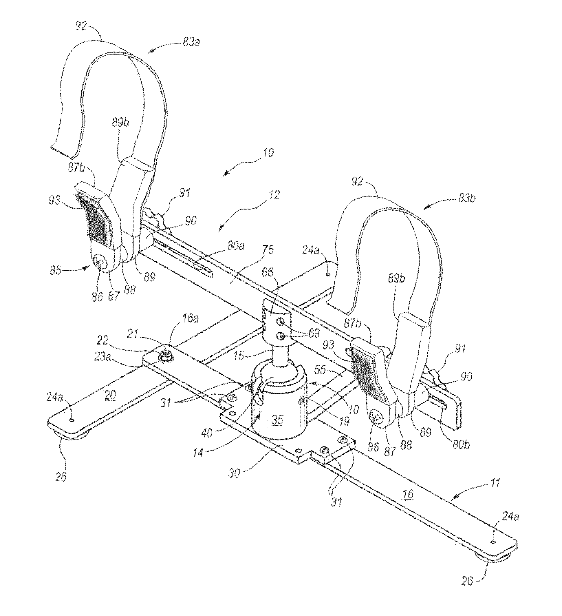
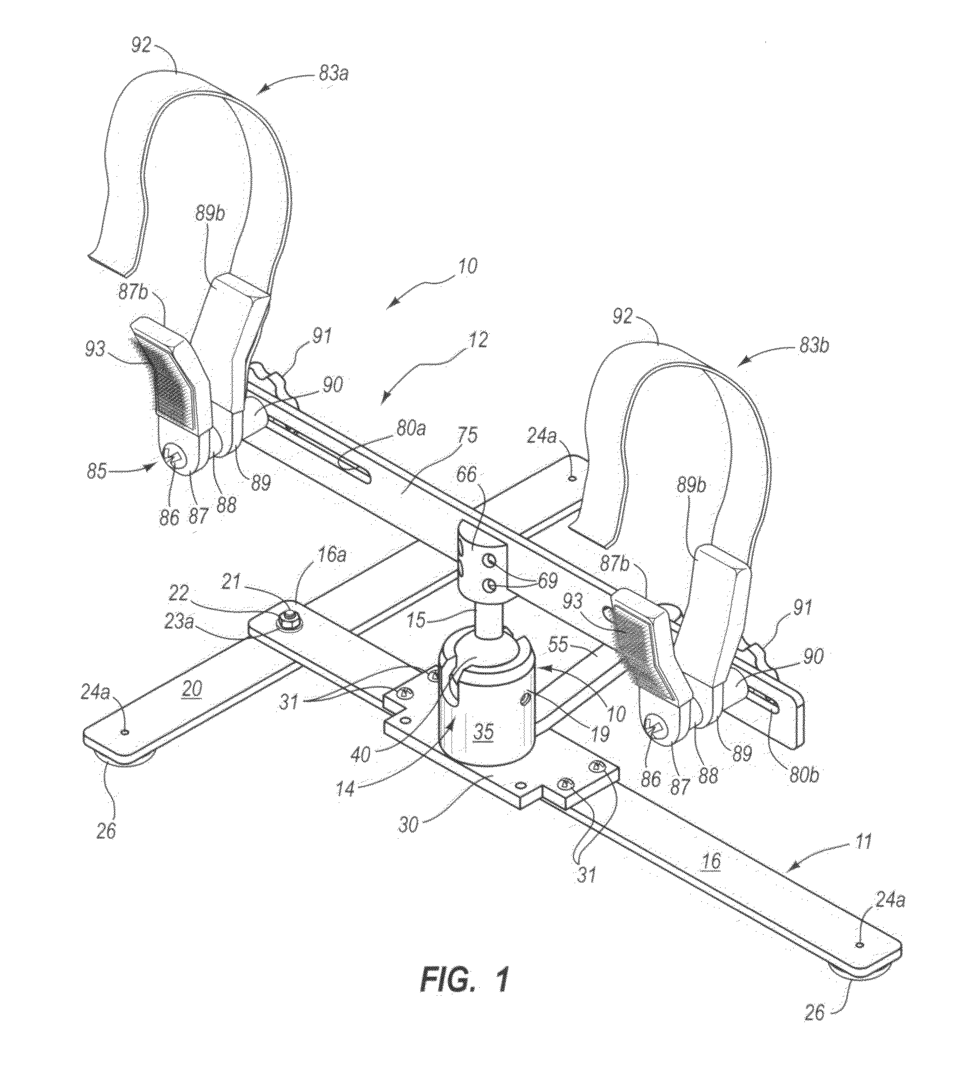
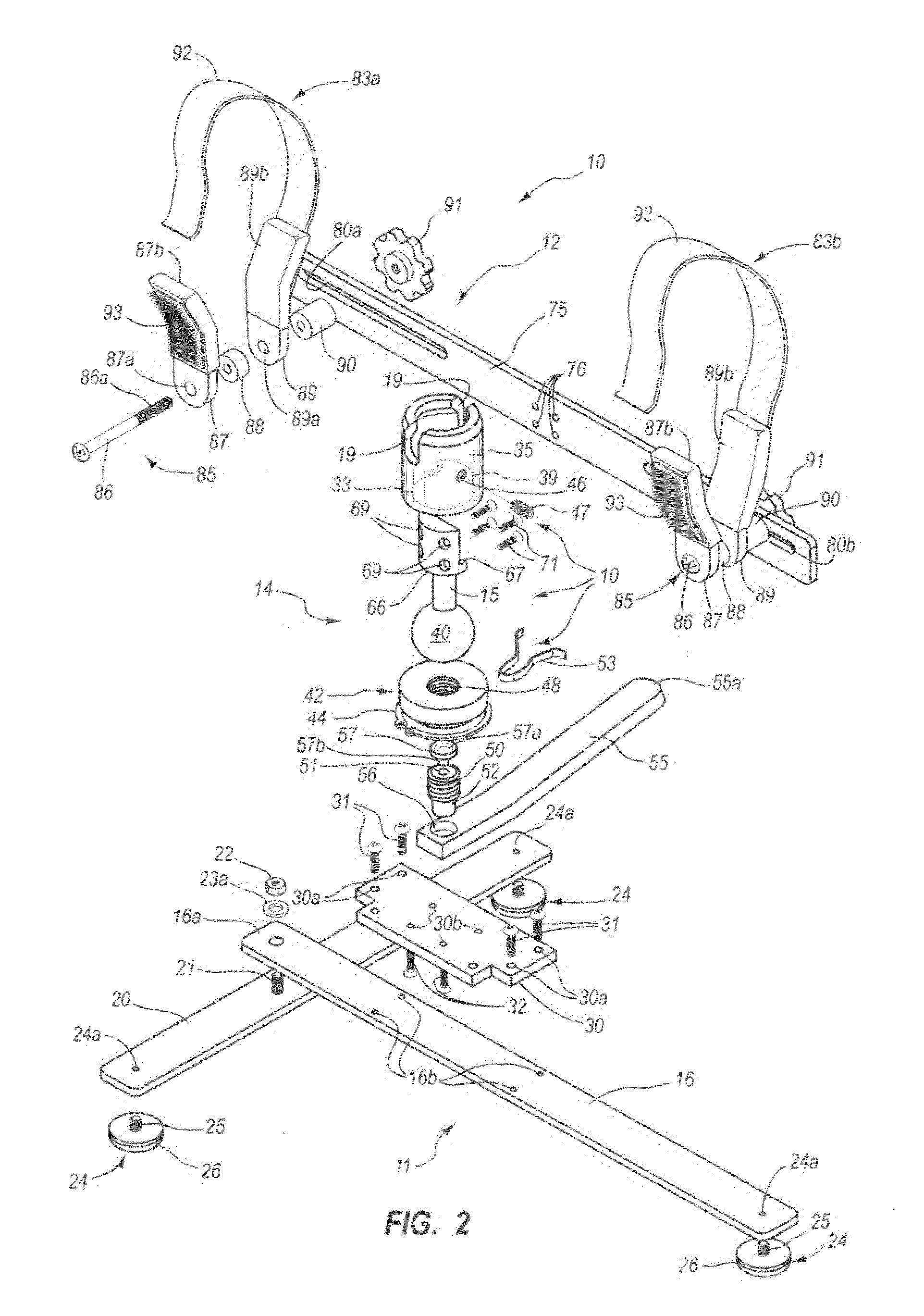
[0043]The invention is an arrangement of a ball joint assembly 14 that, as shown in an exploded view of FIG. 2, includes a housing 35 for connection to a base 30 and contains a round nut 42 fitted therein that a jacking screw 50 is turned through that includes a plunger 51 on a top end thereof that a ball 40 rests on. Which ball 40 includes a shaft or stem 15, hereinafter referred to as stem, that extends through a center opening of a housing cap end 36 whose undersurface is curved to accommodate the ball 40 surface there against, acting as a seat. The stem 15 includes an end coupling 66 that attaches to a work holder, that can be a gun support, bow support, or similar work holding device. The ball joint assembly 14 may be fixed to a workbench, may be connected to a variety of bases, and can be used to support a number of work holding devices that each are arranged to maintain an item or items to be worked on by an operator, providing an operator or user with the ability to quickly ...


PUM

PropertyMeasurementUnit
Angleaaaaaaaaaa
Angleaaaaaaaaaa
Flexibilityaaaaaaaaaa

Abstract

A ball joint assembly and work holding device where the ball joint assembly provides a movable mount for different work holding devices that each provide for holding an item, such as a fire arm, archery bow and / or the like, where the ball joint assembly is for seating on, or mounting onto, a table top, bench, or like surface. The ball joint assembly includes a cylindrical housing slotted on opposite sides thereof from a center opening in the housing top and contains a ball that rests on a plunger top end of a jacking screw that is turned in a round nut by a lever arm, and the ball joint assembly is fitted into the housing. Turning of the lever arm that is fitted through a housing lateral slot extends the plunger top into the ball, lifting the ball to lock it against a housing top concave surface, and which ball includes a stem extending through the housing top to tilt between the slots and pivot when the ball in unlocked, and the ball stem end includes a tool mounting for connection to a work holding devices, and two of which work holding devices: a shooting rest and an archery bow mount are unique to the invention.

Description

BACKGROUND OF THE INVENTION[0001]1. Field of the Invention[0002]This invention relates to a multipurpose ball joint assembly, where the ball joint assembly allows both rotational and tilting movement of the holding device and is easily locked in place and released by a quick release handle and couples to a number of work holding devices.[0003]2. Prior Art[0004]The present invention is a ball joint assembly that includes a stem for mounting a number of work holding devices that each holds an item, such as a fire arm, archery bow, and the like, to allow an operator to perform repairs or adjustments thereon. The ball joint assembly incorporates a right hand pivot arm ball joint lock that is capable of allowing a user to freely rotate and tilt an item being worked on that is connected to the ball stem, and, by locking the ball, provides for maintaining the item being worked on in a variety of positions. The, present invention provides for conveniently locking and maintaining the ball of...

Claims


Application Information

Patent Timeline
IPC IPC(8): A47G29/00F16C11/06
CPCF16C11/106F16M11/041F16M11/14Y10T29/53961F16M2200/022F41A23/16Y10T403/32672F16M13/022F41B5/1449
Inventor LEE, KEVIN J.BERRY, TONY JAMES
Owner BERRYS MFG
Learn More