
Curved mirror camera

a mirror camera and curved technology, applied in the field of curved mirror cameras, can solve the problems of wasting labor and time, and achieve the effects of saving time, convenient adjustment, and easy damag

Inactive Publication Date: 2011-04-28
CHEN KUN SEN
View PDF4 Cites 1 Cited by
  • Summary
  • Abstract
  • Description
  • Claims
  • Application Information

AI Technical Summary

Benefits of technology

"The present invention provides a curved mirror camera that allows for clearer image capture. It includes an opaque housing, a single-sided curved reflector, a light-absorption hood, and a camera. The camera converts the image into an electronic signal for output and is provided with a zoom lens. The invention also provides a hidden-type camera that is not easily damaged by people with indecent intention. The camera allows for convenient adjustment of various parameters and functions through multiple instruction signals. The camera can be controlled and adjusted wirelessly using a remote controller and IP remote transmission, saving time and labor work. Overall, the invention provides a more practical and efficient solution for surveillance and photography applications."

Problems solved by technology

Although a criminal behavior can be deterred, it is actually easier to stop a man of integrity than a villain, as the villain will usually damage the surveillance camera 1 or hide from a lens before committing a crime to prevent crime scenes from being shot.2. A conventional corner reflector which is installed at a location, such as an intersection of a curved road, a corner of a shopping mall, a U-turn place at a traffic lane of a community, is only used for auxiliary surveillance but is really not provided with the surveillance function, which has no physical help to collect evidences of an event, identify a truth and secure the evidences.3. To cope with all kinds of on-site environments, the conventional surveillance camera should be sent back to an original manufacturer to calibrate and adjust every parameter and function by instruments, which wastes labor work and time.4. The surveillance camera should be integrated into the existing reflector, which can avoid installing too many surveillance devices, mitigate constriction to people and improve the shortcomings of effects of all kinds of curved mirrors caused by difference of the curvature.

Method used


Image

  • Curved mirror camera
  • Curved mirror camera
  • Curved mirror camera

Examples


Embodiment Construction

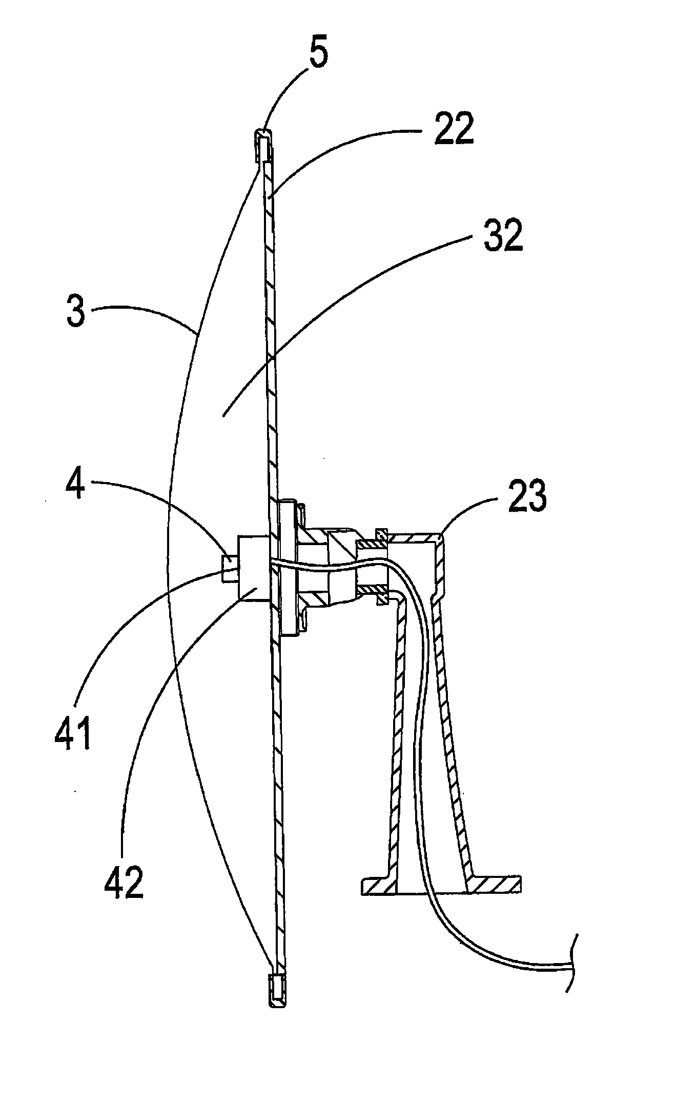
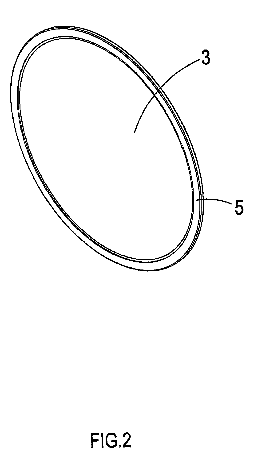
[0023]Referring to FIGS. 2 to 4, it shows a three-dimensional schematic view, a three-dimensional exploded view and a cutaway view, of a preferred embodiment of the present invention. As shown in the drawings, the present invention comprises:

[0024]an opaque housing 2 which is surrounded by a first connection part 21 and is assembled with a bracket 23;

[0025]a single-sided curved reflector 3, which is assembled with the opaque housing 2, a periphery of which is provided with a second connection part 31 being assembled with the first connection part 21 as one unit by using a collar 5 and which is assembled with the opaque housing 2 to form an internal accommodation space 32, with transmittance of the single-sided curved reflector 3 being controlled to be at 4% to 20% and the single-sided curved reflector 3 being optically transparent PMMA (Polymethyl methacrylate) acryl, optically transparent PC (Polycarbonate) or optically transparent glass, allowing infrared at a wavelength of 800 nm...


PUM


Abstract

The present invention discloses a curved mirror camera including an opaque housing, a single-sided curved reflector, a light-absorption hood and a camera. The opaque housing contains an opening, the single-sided curved reflector is assembled with the opaque housing to form an internal accommodation space, the light-absorption hood is collected in the accommodation space and the camera is collected in the accommodation space. The camera converts an image into an electronic signal for output and is further provided with a zoom lens by which a same photographing effect of shiny mirror reflection, high quality and high definition can be provided, so as to improve an issue in a conventional camera wherein a lens is always fixed.

Description

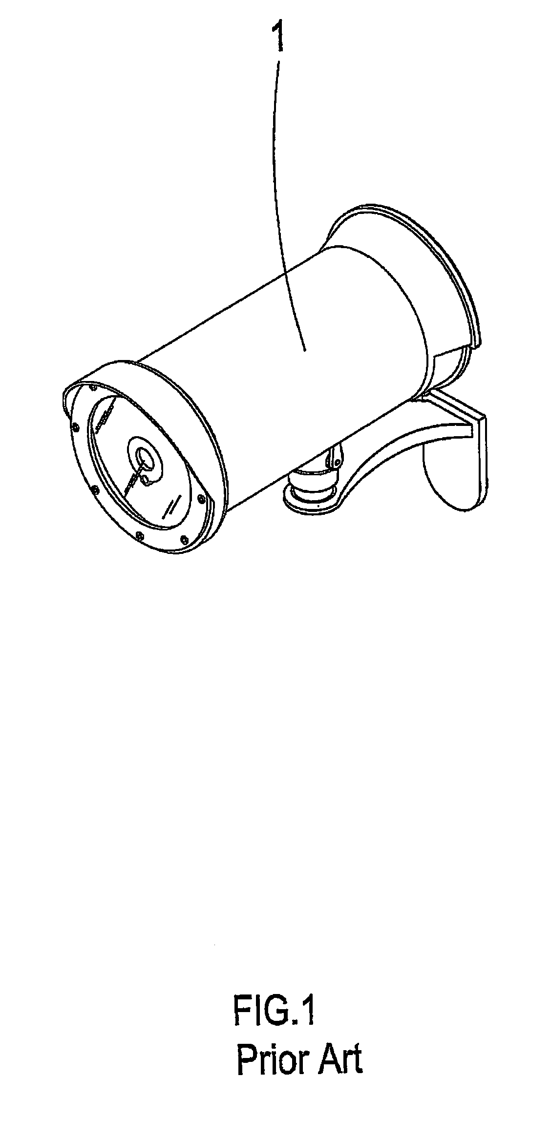
BACKGROUND OF THE INVENTION[0001]a) Field of the Invention The present invention relates to a curved mirror camera, and more particularly to a curved mirror camera which is provided with a zoom lens.[0002]b) Description of the Prior Art[0003]As emerging of counter-terrorism, a surveillance camera apparatus has been very broadly applied, and in a daily life, the surveillance camera apparatus is indeed very important for fighting a crime and securing evidences. However, when using the aforementioned surveillance camera apparatus, following issues and shortcomings actually exist to be improved:[0004]1. Referring to FIG. 1, it shows a three-dimensional view of a conventional surveillance camera. The surveillance camera 1 is usually installed at a location that is too clear. Although a criminal behavior can be deterred, it is actually easier to stop a man of integrity than a villain, as the villain will usually damage the surveillance camera 1 or hide from a lens before committing a crim...

Claims


Application Information

Patent Timeline
Patent Type & Authority Applications(United States)
IPC IPC(8): H04N7/18H04N5/33
CPCG03B37/00H04N7/18H04N5/23206G08B13/19626H04N23/50
Inventor CHEN, KUN-SEN
Owner CHEN KUN SEN
Learn More