
Single Frequency User Ionosphere System and Technique

Inactive Publication Date: 2011-03-03
RAYTHEON CO
View PDF2 Cites 11 Cited by
  • Summary
  • Abstract
  • Description
  • Claims
  • Application Information

AI Technical Summary

Benefits of technology

[0010]With this particular arrangement, a GPS receiver that continuously estimates ionospheric delay during flight for each measured satellite regardless of bubble, depletion, and / or scintillation distortion effects is provided. By continuously estimating ionospheric delay during flight for each measured satellite regardless of distortion, the receiver is more accurate than prior art GPS receivers. In one embodiment, the GPS receiver continuously tracks / estimates ionospheric residual delay and phase ambiguity during flight and follows the distortion for each visible satellite with an optimal filter. New satellites coming up can be initialized using existing user position data. Thus, the receiver allows a single frequency user to utilize measurements with the ionosphere depletion. This leads to better receiver availability and accuracy for GPS navigation systems in equatorial regions or in any application is which measurements include distortion effects.

Problems solved by technology

Current Satellite-Based Augmentation Systems (SBAS) in the mid magnetic latitudes can provide a certain level of precision guidance for single frequency users; however, the ionospheric phenomena typically found at the equatorial latitudes significantly challenges current SBAS approaches to precision guidance.
The three major phenomena causing the challenging accuracy distortions are the equatorial anomaly, depletion features (bubbles), and scintillations.
The equatorial ionosphere anomaly is an age-old problem that affects navigation systems.
However, the ionosphere delay is substantial in the measurement and yet unknown which gives uncertainty to the ranging estimates to the satellites.
In active ionosphere activity regions near the equator, however, the coarse grids often miss the peaks and valleys in the ionosphere charge distribution (called the residuals), and / or the user's LOS may have charge depletion zones (also called “bubbles”) that are not viewable from the ground stations.
These distortion effects (also including scintillation) can cause considerable errors in the user's estimate of the ionosphere delay.
Thus, this approach reduces the number of GPS satellites processed for navigation.
One problem with the approach, however, is that in equatorial regions, depletions may be prevalent, and if too many measurements are thrown out, there may not be enough remaining satellites with which to perform accurate ranging.
This reduces the availability, the accuracy, and the continuity of the navigation system.

Method used


Image

  • Single Frequency User Ionosphere System and Technique
  • Single Frequency User Ionosphere System and Technique
  • Single Frequency User Ionosphere System and Technique

Examples


Embodiment Construction

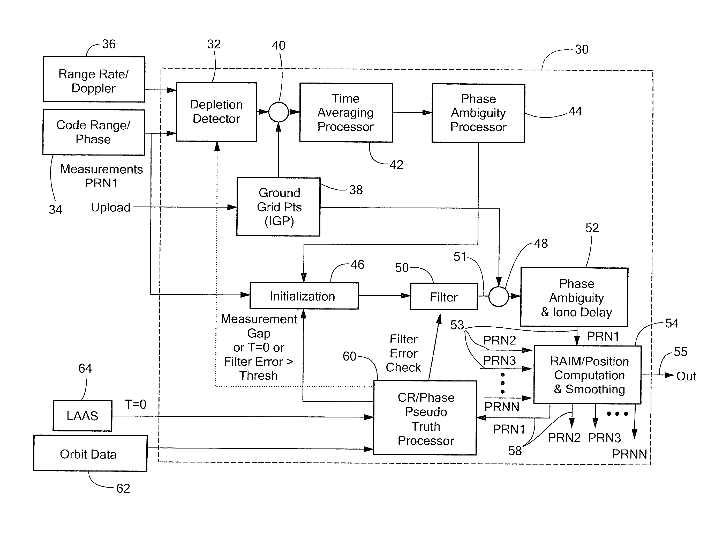
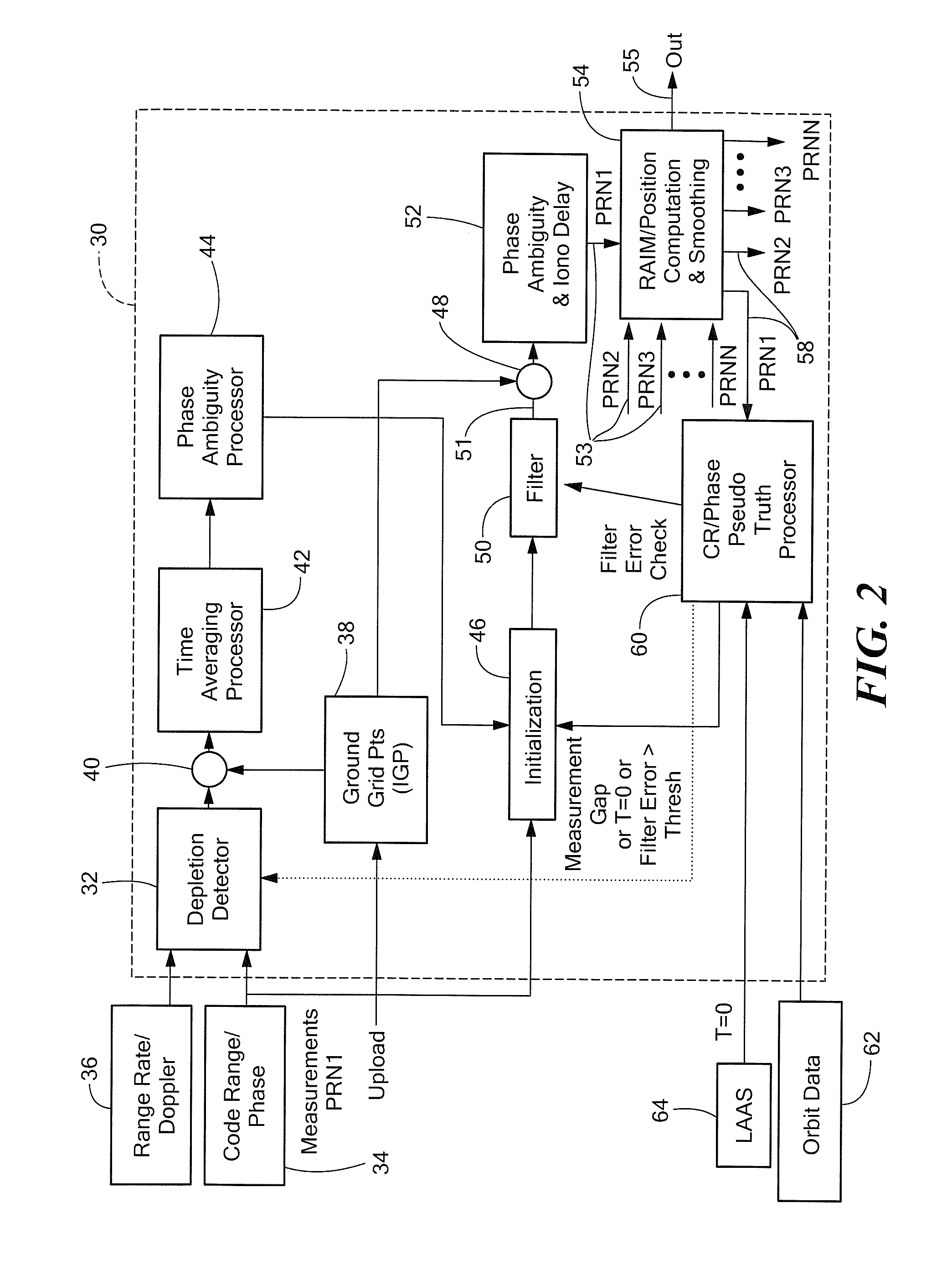
[0023]Described herein are systems and techniques for directly estimating depleted or residual ionosphere delay and using the estimate for navigation in an aircraft. Before describing such systems and related techniques, some introductory concepts and terminology are explained.

[0024]Reference is sometimes made herein to systems and techniques which include filters. It should be appreciated, however, that in some embodiments filters are not required. For example, in one embodiment, a User Ionosphere Vertical Error (UIVE) value is derived from GIVE grid point data interpolation and user measurement error estimation. The UIVE value is then used to select a historically best set of IGDs for phase ambiguity estimation. Thus, in such an embodiment, the UIVE estimate is made and when it is determined that the UIVE estimate is at an acceptable value (or within an acceptable range of values) based upon historic data, that UIVE estimate is used to select the ambiguity estimate and no filter i...


PUM


Abstract

A method and apparatus for directly estimating depleted ionosphere delay in a GPS receiver and using the estimate for improved navigation precision in satellite based augmentation systems.

Description

CROSS-REFERENCE TO RELATED APPLICATIONS[0001]This application CLAIMS PRIORITY to U.S. Provisional Application Ser. No. 61 / 236,601, filed on Aug. 25, 2009 (Attorney Docket No. RTN-535PUSP), which is incorporated herein by reference in its entirety.FIELD OF THE INVENTION[0002]The system and techniques described herein relate generally to navigation systems, including but not limited to air traffic control systems and more particularly to a method and apparatus for directly estimating depleted or residual ionosphere delay and using the estimate for navigation in an aircraft.BACKGROUND OF THE INVENTION[0003]Current Satellite-Based Augmentation Systems (SBAS) in the mid magnetic latitudes can provide a certain level of precision guidance for single frequency users; however, the ionospheric phenomena typically found at the equatorial latitudes significantly challenges current SBAS approaches to precision guidance. The three major phenomena causing the challenging accuracy distortions are ...

Claims


Application Information

Patent Timeline
IPC IPC(8): G01S19/44
CPCG01S19/07G01S19/072
Inventor UM, GREGORY S.BIGGS, MARK WAYNESCHEMPP, TIMOTHY
Owner RAYTHEON CO
Features
  • Generate Ideas
  • Intellectual Property
  • Life Sciences
  • Materials
  • Tech Scout
  • Unparalleled Data Quality
  • Higher Quality Content
  • 60% Fewer Hallucinations
Learn More