
Gas Boost Circulation System

a circulation system and gas boost technology, applied in the direction of positive displacement liquid engine, fluid removal, borehole/well accessories, etc., can solve the problems of gas locking, head degradation, and separator not being integrated,

Active Publication Date: 2010-12-23
BAKER HUGHES INC
View PDF12 Cites 48 Cited by
  • Summary
  • Abstract
  • Description
  • Claims
  • Application Information

AI Technical Summary

Benefits of technology

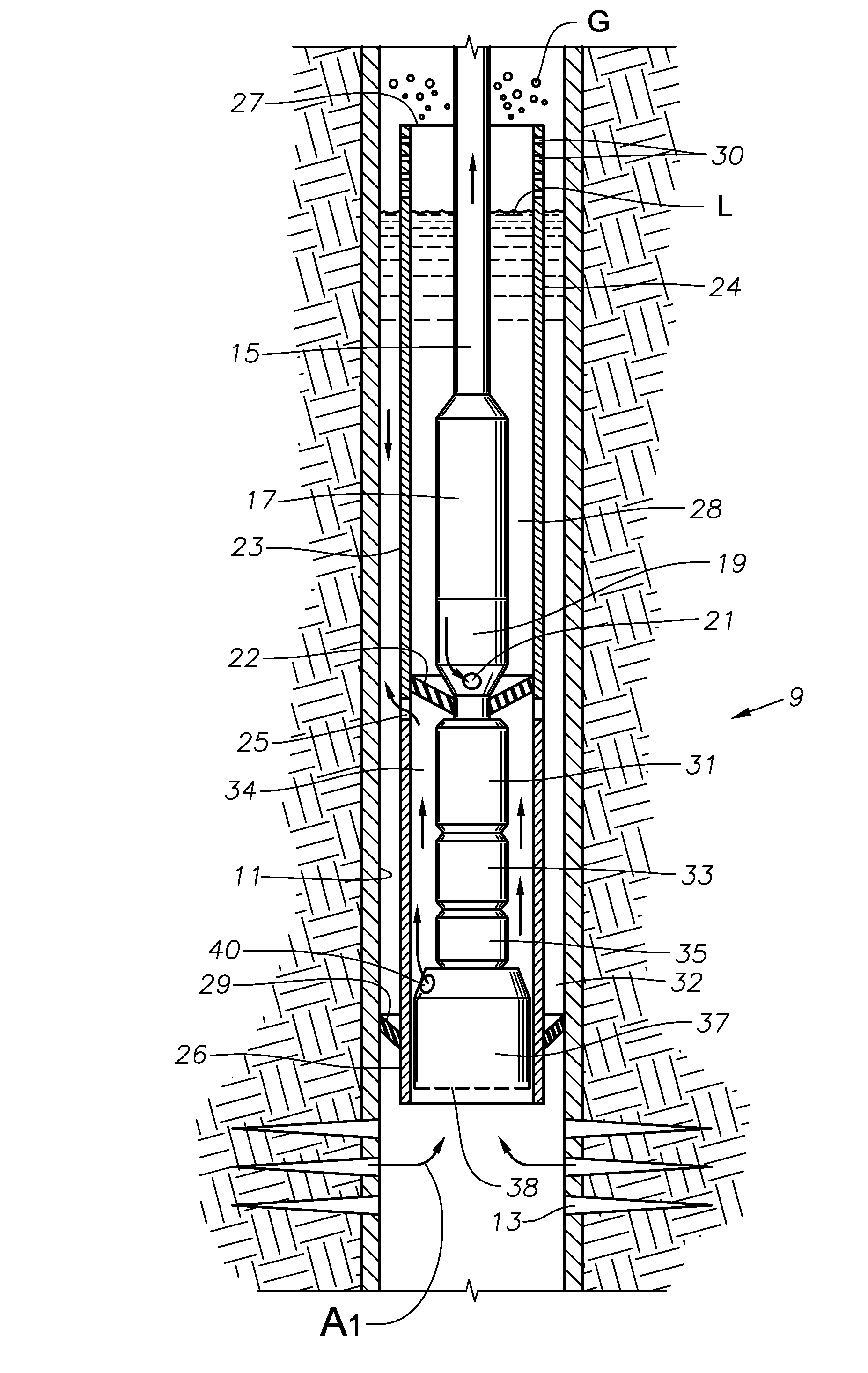
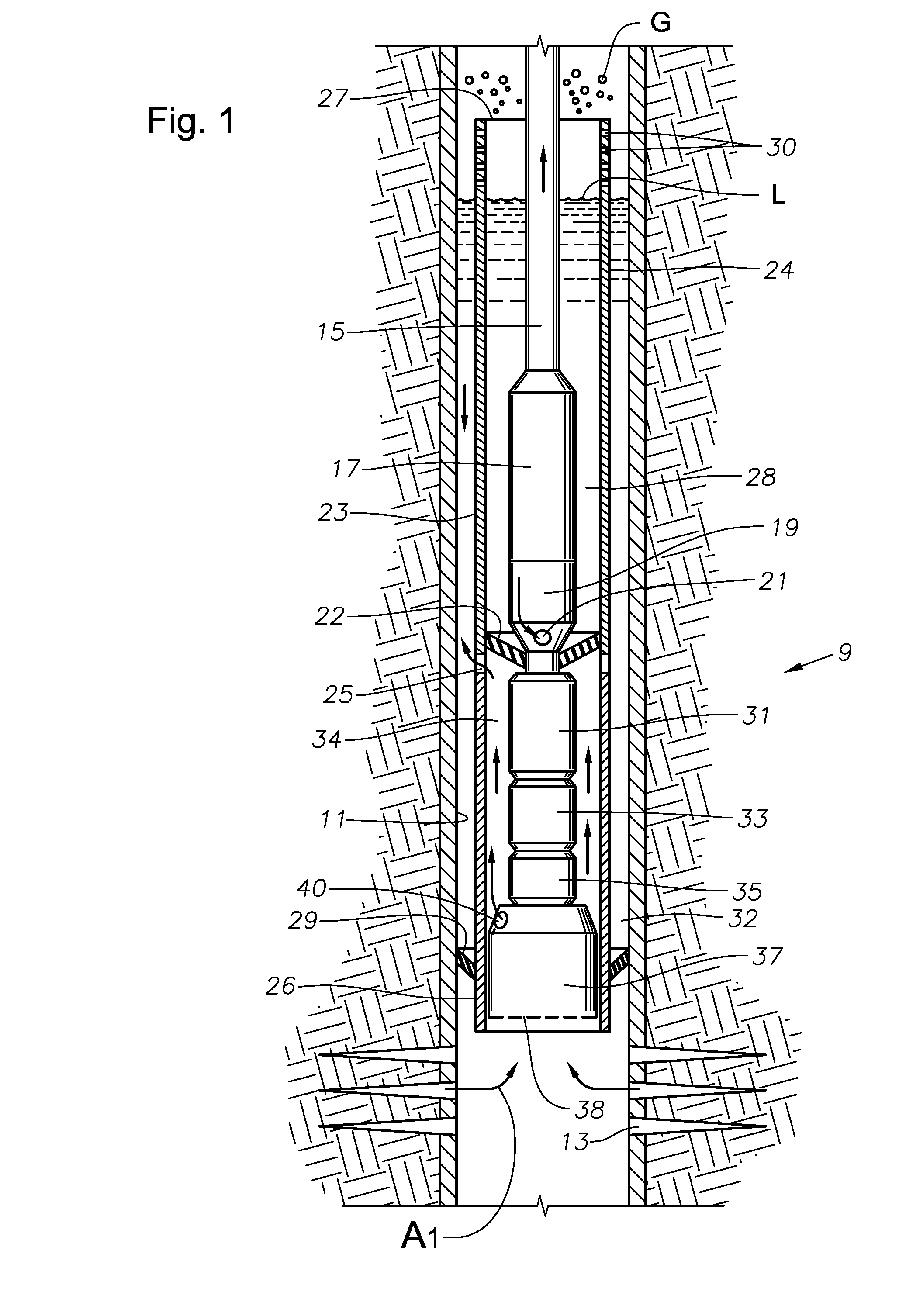
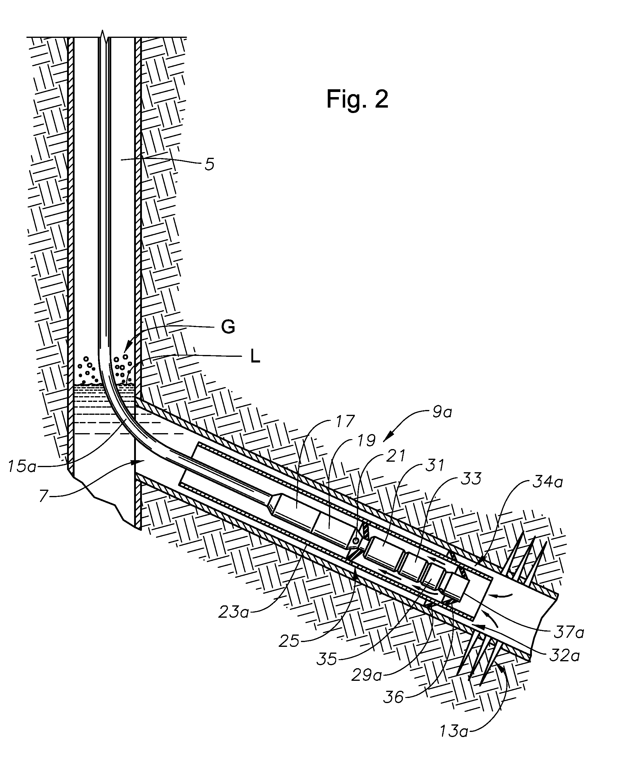
The patent describes a system and method for producing wellbore fluids. The system includes a submersible pumping system with a booster pump and a liquid lift pump. The booster pump is placed below the liquid lift pump and is powered by a motor. The booster pump is designed to separate gas from the multi-phase fluid and to pump it up the annulus surrounding the wellbore. The system also includes a shroud that encloses the motor and the inlet of the liquid lift pump. The booster pump is positioned below the liquid lift pump and is powered by the motor. The system is designed to separate gas from the wellbore fluid and to pump it up the annulus surrounding the wellbore. The technical effect of this patent is to provide an improved system for producing wellbore fluids with a high gas-to-liquid ratio.

Problems solved by technology

Centrifugal pumps are mainly designed to handle liquid and will suffer from head degradation and gas locking in the presence of a high percentage of free gas.
Normally, a gas separator would not be incorporated with a shrouded ESP because of the problem of disposing of the gas into the well fluid flowing toward the inlet of the shroud.
If the shroud inlet is on the upper end, any gas discharged from the gas separator would flow upward through the annulus surrounding the shroud and might fail to separate from the liquid at the inlet of the shroud where the well fluid begins flowing downward.

Method used


Image

  • Gas Boost Circulation System
  • Gas Boost Circulation System
  • Gas Boost Circulation System

Examples


Embodiment Construction

[0021]The apparatus and method of the present disclosure will now be described more fully hereinafter with reference to the accompanying drawings in which embodiments are shown. This subject of the present disclosure may, however, be embodied in many different forms and should not be construed as limited to the illustrated embodiments set forth herein; rather, these embodiments are provided so that this disclosure will be thorough and complete, and will fully convey the scope of the invention to those skilled in the art. Like numbers refer to like elements throughout. For the convenience in referring to the accompanying figures, directional terms are used for reference and illustration only. For example, the directional terms such as “upper”, “lower”, “above”, “below”, and the like are being used to illustrate a relational location.

[0022]It is to be understood that the subject of the present disclosure is not limited to the exact details of construction, operation, exact materials, ...


PUM


Abstract

A submersible well pump assembly in a wellbore; the pump assembly includes a liquid lift pump and a booster pump for pumping a two-phase mixture of gas and liquid. A shroud with an opening at its upper end partially encloses the pump assembly. An annulus is formed between the shroud and the wellbore inner circumference. Two phase fluid from the booster pump exits the shroud through a port and flows up the annulus to the shroud opening. Liquid in the two-phase flow separates from the gas and flows into the shroud opening and onto the liquid lift pump. The gas continues to flow up the wellbore, past the shroud opening, to the wellbore entrance.

Description

BACKGROUND[0001]1. Field of Invention[0002]The present disclosure relates in general to electrical submersible well pumps. More particularly, the present disclosure is directed to a submersible pump assembly that includes a liquid lift pump and a two phase fluid booster pump disposed in an inverted shroud. Two phase fluid is propelled from the booster pump to the shroud entrance where liquid separates and flows to the liquid lift pump.[0003]2. Description of Prior Art[0004]An electrical submersible pump assembly (ESP) for a well typically includes a centrifugal pump driven by a submersible electrical motor. The ESP is normally installed within the well on tubing. Many wells produce a combination of oil and water as well as some gas. Centrifugal pumps are mainly designed to handle liquid and will suffer from head degradation and gas locking in the presence of a high percentage of free gas. Several techniques have been developed to remove the gas before it enters the pump.[0005]One te...

Claims


Application Information

Patent Timeline
Patent Type & Authority Applications(United States)
IPC IPC(8): E21B43/00F04B23/08
CPCE21B43/128F04B47/06F04B23/08
Inventor REID, LESLIE C.
Owner BAKER HUGHES INC
Learn More