
Multiple suture thread configuration with an intermediate connector

a multi-suture thread and connector technology, applied in the field of suture anchoring, can solve the problems of time-consuming, difficult and inefficient conventional methods for approximating tissue to bone using a suture, and difficult procedures

Inactive Publication Date: 2010-12-16
ETHICON INC +1
View PDF106 Cites 46 Cited by
  • Summary
  • Abstract
  • Description
  • Claims
  • Application Information

AI Technical Summary

Benefits of technology

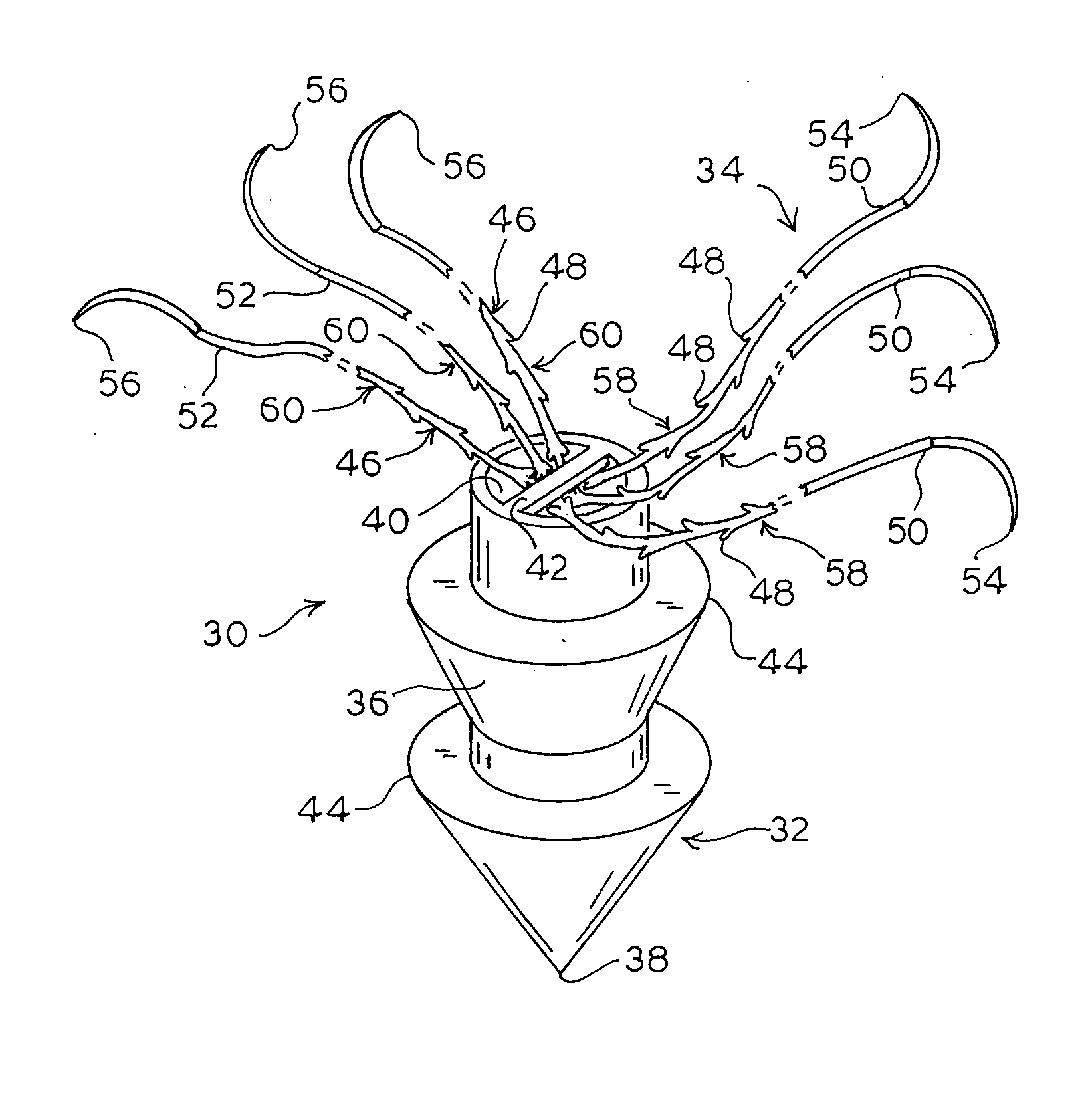
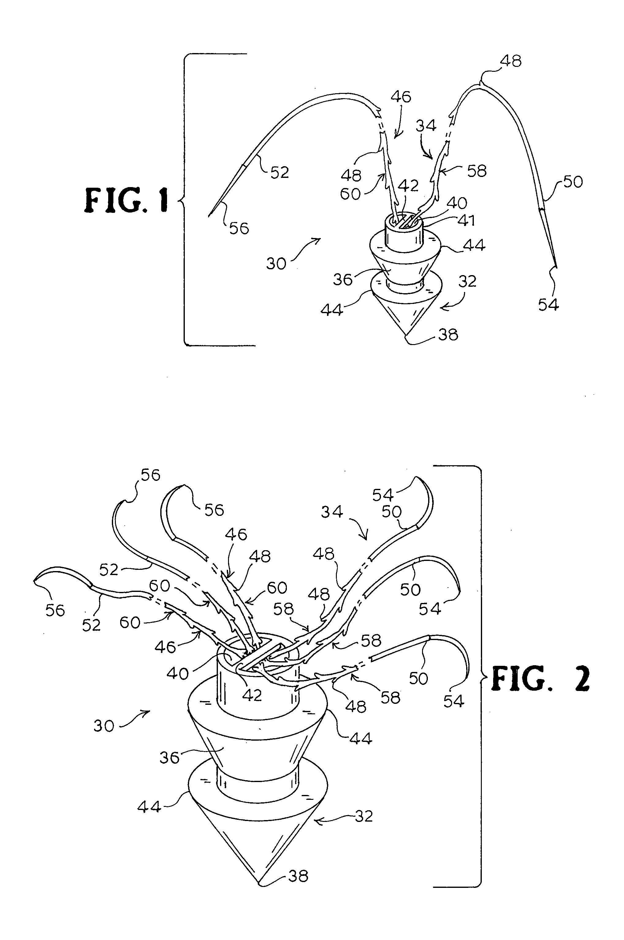
[0008]According to the present invention, a suture anchor is provided for approximating tissue to bone or other tissue. The suture comprises an anchor member adapted to fixedly engage the bone for securing the anchor member relative to the bone. A plurality of sutures are mounted to the proximal end of the anchor member so that the sutures extend outwardly from the anchor member. Each suture has a sharp pointed distal end for penetrating the tissue and a plurality of barbs extending from the periphery of the body. The barbs permit movement of the sutures through the tissue in a direction of movement of the pointed end and prevent movement of the sutures relative to the tissue in a direction opposite the direction of movement of the pointed end.

Problems solved by technology

However, these procedures are often difficult to perform, particularly in areas with limited access, such as deep wounds.
Further, conventional methods for approximating tissue to bone using a suture are difficult and inefficient because the procedure requires manipulation of the suture for securing the tissue in place.
This is a time-consuming part of most surgical procedures, particularly in microsurgery and endoscopic surgery where there is insufficient space to properly manipulate the suture.

Method used


Image

  • Multiple suture thread configuration with an intermediate connector
  • Multiple suture thread configuration with an intermediate connector
  • Multiple suture thread configuration with an intermediate connector

Examples


Embodiment Construction

[0020]As used herein, the term “tissue” includes tendons, ligaments, cartilage, muscle, skin, organs, and other soft tissue. The term “bone” includes bone, cartilage, tendon, ligament, fascia, and other connective or fibrous tissue suitable for anchor for a suture.

[0021]Certain other terminology is used herein for convenience only and is not to be taken as a limitation on the invention. For example, words such as “upper,”“lower,”“left,”“right,”“horizontal,”“vertical,”“upward,” and “downward” merely describe the configuration shown in the FIGs. It is understood that the components may be oriented in any direction and the terminology, therefore, should be understood as encompassing such variations unless specified otherwise.

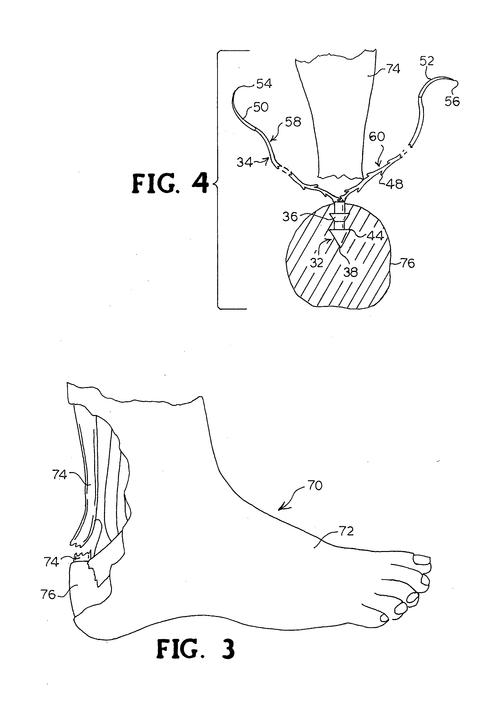
[0022]Referring now to the drawings, wherein like reference numerals designate corresponding or similar elements throughout the several views, there is shown in FIG. 1 a suture anchor for use according to the present invention and generally designated at 30. The su...


PUM


Abstract

A suture system has a plurality of barbed sutures each with a plurality of barbs and a body connector that connects said plurality of barbed sutures. The sutures can move relative to the body connector. The body connector can retain tissue.

Description

CLAIM TO PRIORITY[0001]This application is a continuation of U.S. application Ser. No. 12 / 119,749, filed May 13, 2008, now pending; which is a divisional of U.S. application Ser. No. 10 / 914,755, filed Aug. 9, 2004, now U.S. Pat. No. 7,371,253, issued May 13, 2008; which is a divisional of U.S. application Ser. No. 10 / 216,516, filed Aug. 9, 2002, now U.S. Pat. No. 6,773,450, issued Aug. 10, 2004. All of the above claimed priority applications are incorporated herein by reference in their entireties.BACKGROUND OF THE INVENTION[0002]This invention relates generally to a device and method for anchoring tissue within a body and, more particularly, to a suture anchor for use in surgical procedures requiring attachment of tissue, such as ligaments, tendons and the like, to other, preferably harder or more fibrous, tissue, such as a bone surface.[0003]Suture anchors are used in surgical procedures wherein it is necessary for a surgeon to attach tissue to the surface of bone, for example, du...

Claims


Application Information

Patent Timeline
Patent Type & Authority Applications(United States)
IPC IPC(8): A61B17/04A61B17/06A61B17/11
CPCA61B17/0401A61B17/06166A61B17/064A61B17/1146A61B2017/0412Y10S606/91A61B2017/0462A61B2017/06057A61B2017/06176Y10S606/908A61B2017/0427
Inventor LEUNG, JEFFREY C.RUFF, GREGORYKAPLAN, ANDREW
Owner ETHICON INC
Learn More