
Tongue block

Inactive Publication Date: 2010-11-18
SHIH J RICHARD +1
View PDF7 Cites 10 Cited by
  • Summary
  • Abstract
  • Description
  • Claims
  • Application Information

AI Technical Summary

Problems solved by technology

They are effective for general dental procedure but can not effectively to prevent tongue cutting when patients are sedated.
This appliance is not effective to block the tongue out of surgeon's instrumentation.
The device is quite complex and do not have concave mirror surface to reflect the light.
This appliance is not designed for blocking the tongue.

Method used


Image

  • Tongue block
  • Tongue block
  • Tongue block

Examples


Embodiment Construction

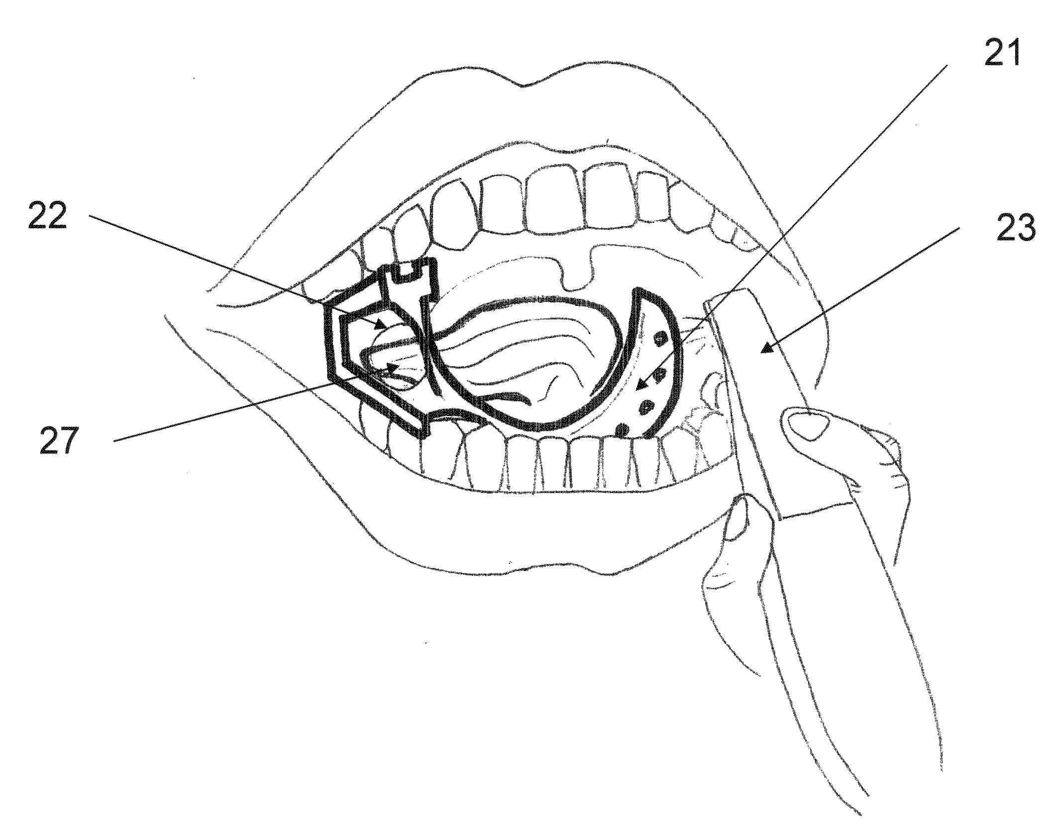
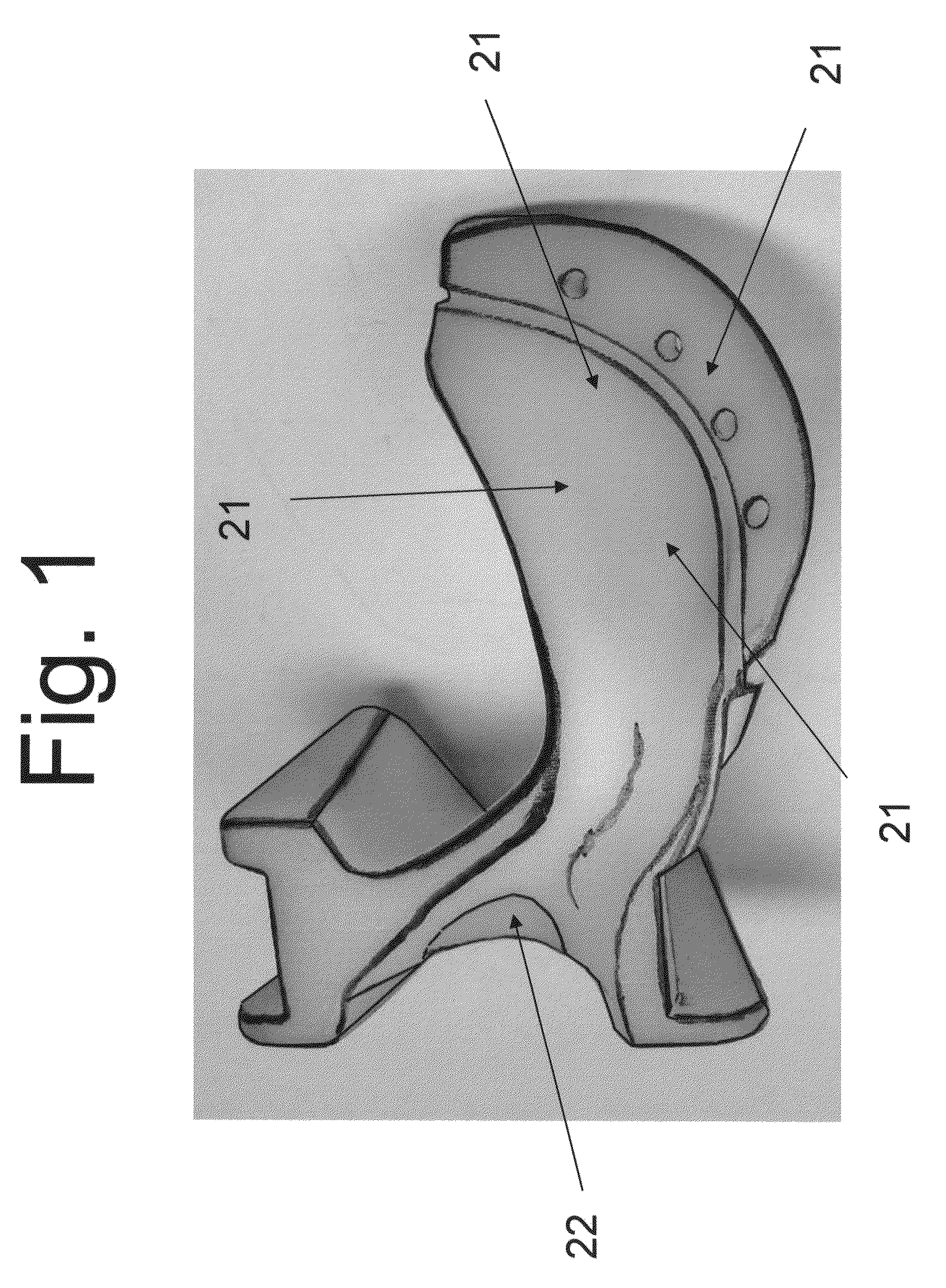
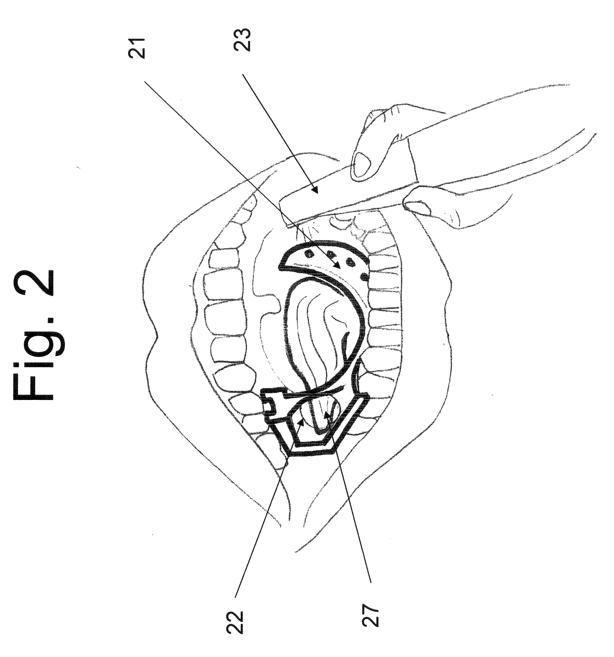
[0019]The purpose of the invention is to provide an improved device for supporting the jaws in the open position during dental surgery and treatment in a manner that will facilitate use of instruments by the dental practitioner and will protect the patient's tongue by instruments in the patient's mouth during dental procedures while patient is sedated and tongue get enlarged because of sedation. The device is simple and economical enough to occasion wide use. Because the device is inexpensive, it can be sold as a disposable unit. Use of such disposable devices avoids expense of cleaning and spread of infection.

[0020]The device of the invention consists essentially of a bite block with an elongated portion that extends from the anterior aspect of the block so that the elongated portion is deflected to provide a physiological shape elongation and flange to act as tongue blocking device. The u-shape physiologically curved elongated portion extends around the inside the dentition from b...


PUM


Abstract

The invention is a device for use as a prop to hold the mouth open which consists essentially of a bite block with an elongated portion that is deflected and to provide a physiologically shaped elongated portion extends along the buccal border of the tongue to form a tongue depressor and light reflector as the bite block is held in position. The retaining arm, tongue guiding hole and the flange retain the patient's tongue in the bottom cavity of the patient's mouth.

Description

[0001]This application is a continuation-in-part of U.S. Ser. No. 10 / 697,932, filed Oct. 31, 2003, which is now abandoned.FIELD OF THE INVENTION[0002]The present invention relates to an dental / medical device.BACKGROUND OF THE INVENTION[0003]The subject invention is a prop for holding the mouth open to be used during oral surgery and during dental treatment and repair. The device is particularly valuable when caring for an uncooperative or incompetent patient under sedation, which will reduce the trauma or cutting tongue during the treatment procedure. The invention is also helpful as a tool to suppress tongue position when taking CAD / CAM digital impression, which greatly reduces the chair time for such a procedure.DESCRIPTION OF THE PRIOR ART[0004]Many prop devices, with or without suction means, are available to the dentist and oral surgeon. However, an adaptation of the relatively simple prop disclosed in U.S. Pat. No. 2,220,674 continues to be used. That patent discloses and clai...

Claims


Application Information

Patent Timeline
IPC IPC(8): A61C19/00A61B1/247
CPCA61C5/14A61B2019/204A61B90/16A61C5/90
Inventor SHIH, J. RICHARDSHIH, STEPHANIE TZE-FAN
Owner SHIH J RICHARD
Learn More