
Linear Vibrator

a vibrator and linear technology, applied in the field of vibrators, can solve problems such as increasing the height of the vibrator

Active Publication Date: 2010-08-26
AMERICAN AUDIO COMPONENTS +1
View PDF8 Cites 120 Cited by
  • Summary
  • Abstract
  • Description
  • Claims
  • Application Information

AI Technical Summary

Benefits of technology

The present invention is about a linear vibrator that includes a housing with a base and a cover, elastic members connected to the housing, a vibrating unit suspended in the housing by the elastic members, and a coil positioned in the housing. The base has a bottom wall and a plurality of sidewalls extending vertically from the bottom wall. The vibrating unit has a magnet assembly and vibrates along a direction parallel to the bottom wall. The technical effect of this invention is to provide a linear vibrator that can efficiently generate vibrations in a direction parallel to the bottom wall of the housing.

Problems solved by technology

However, the movement along the direction perpendicular to the mounting surface increases the height of the vibrator.

Method used


Image

  • Linear Vibrator
  • Linear Vibrator
  • Linear Vibrator

Examples


first embodiment

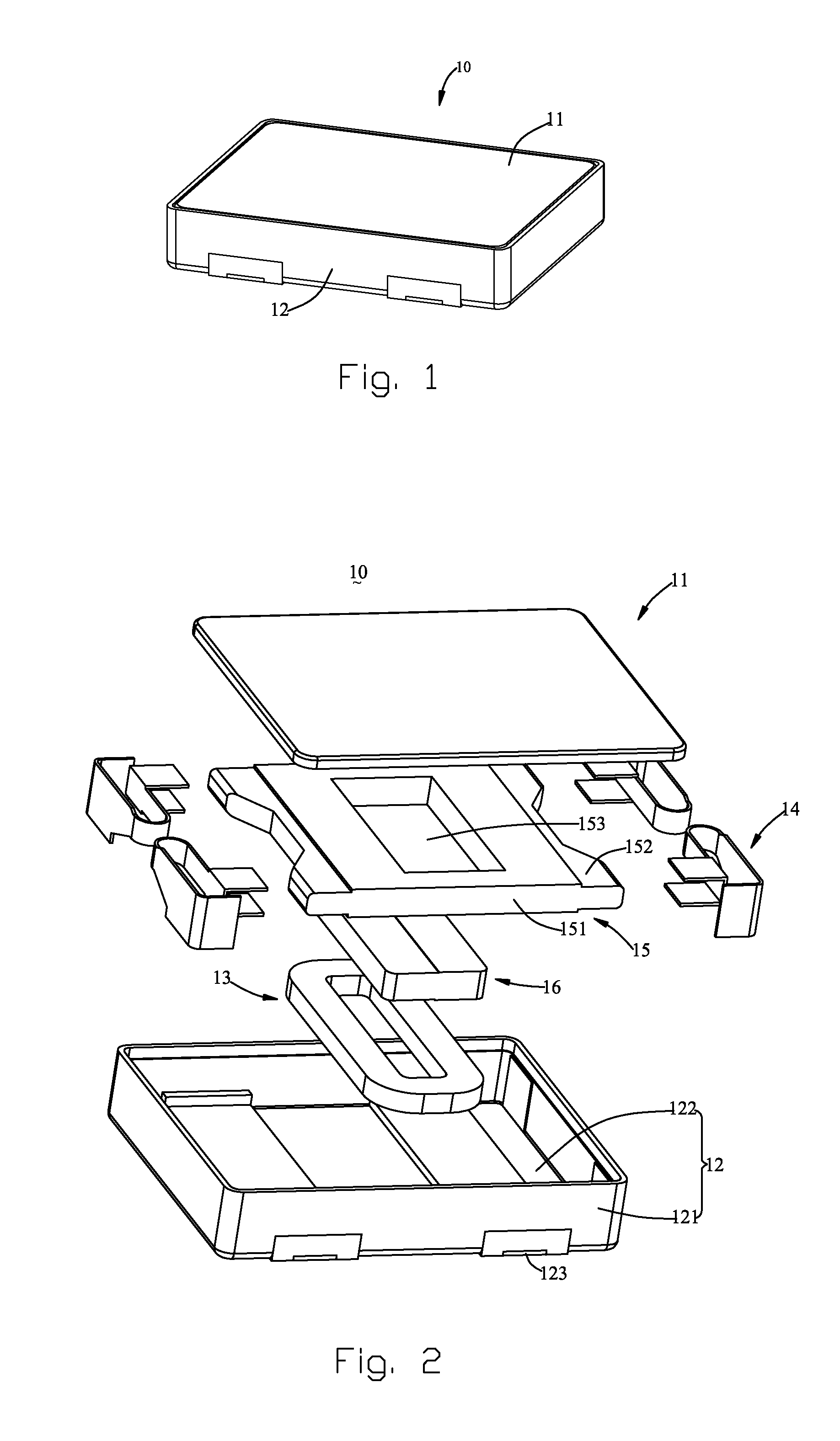
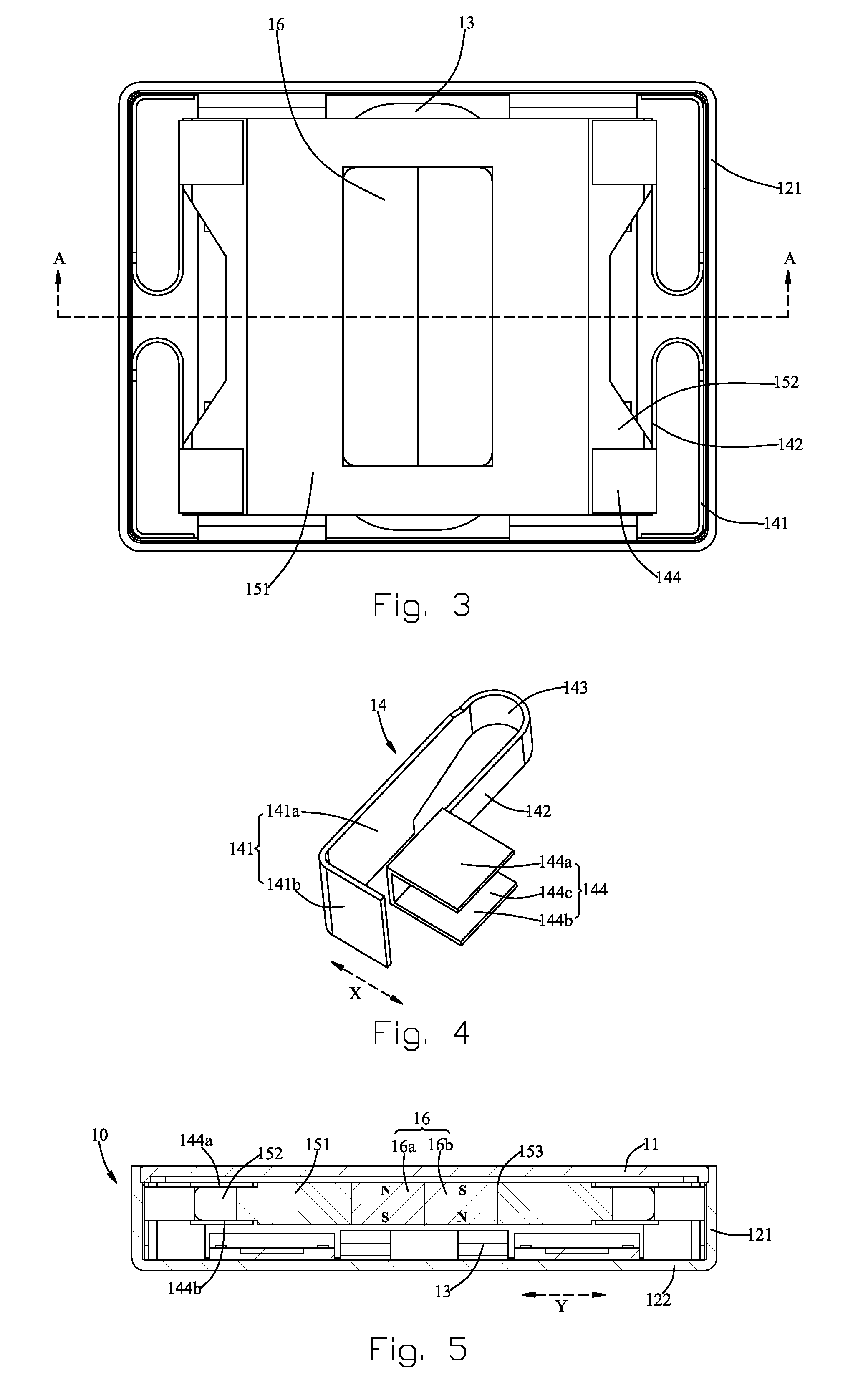
[0015]A linear vibrator is mounted on a printed circuit board for generating tactile vibration. Referring to FIGS. 1-3, a linear vibrator 10, in accordance with the present invention, includes a cover 11, a base 12 forming a receiving space together with the cover 11, an annular coil 13, a plurality of elastic member 14, a weight 15, and a magnet assembly 16. The cover 11 and the base 12 corporately form a housing having the receiving space. The base 12 further defines a bottom wall 122 and a plurality of sidewalls 121 extending vertically from the bottom wall 122. When the vibrator 10 is mounted on the printed circuit board, the bottom wall 122 is attached and parallel to the printed circuit board.

[0016]The coil 13 is positioned on the bottom wall 122 and a pair of leads thereof is electrically connected to electrical pads 123 embedded in the bottom wall 122 for receiving current from external circuits. The elastic members 14 are positioned on the base 12, preferably on the sidewal...

second embodiment

[0019]FIG. 7 illustrates a linear vibrator in accordance with the present invention. In the linear vibrator, two magnets 17, 18 are provided in the weight 15. One of the magnets has magnetic poles opposite to those of another. In fact, it is clearly that the two magnets can be regarded as a magnet assembly.

[0020]As the direction of vibration is parallel to the bottom wall, a height of the linear vibrator can be reduced.


PUM


Abstract

A linear vibrator is disclosed. The linear vibrator includes a housing having a base and a cover, a number of elastic members connected to the housing, a vibrating unit suspended in the housing by the elastic members, and a coil positioned in the housing. The base has a bottom wall and a plurality of sidewalls extending vertically from the bottom wall. The vibrating unit has a magnet assembly and vibrates along a direction parallel to the bottom wall.

Description

FIELD OF THE INVENTION[0001]The present invention generally relates to the art of vibrators and, more particularly, to a linear vibrator for generating tactile sensation.DESCRIPTION OF RELATED ART[0002]Consumer products, such as mobile phones and portable multi-media players, generally include vibrators for generating tactile feedback. For example, a mobile phone has a vibrator for generating vibration while a call is called in, and a portable multi-media player has a touch screen having vibrators for getting tactile feedback.[0003]A vibrator has a moving unit moving along a linear direction is called linear vibrator. Linear vibrators are widely used in consumer products and are disclosed in U.S. Pat. No. 6,466,682 B2 issued on Oct. 15, 2002, and U.S. Pat. No. 7,099,489 B2 issued on Aug. 29, 2006. The vibrator is mounted on a mounting surface of a printed circuit board, and the moving unit thereof is actuated to move along a direction perpendicular to the mounting surface. However, ...

Claims


Application Information

Patent Timeline
Patent Type & Authority Applications(United States)
IPC IPC(8): H02K33/16
CPCH02K33/16
Inventor DONG, LE-PINGPU, YONG-HUA
Owner AMERICAN AUDIO COMPONENTS
Learn More