
Muffin baker

Active Publication Date: 2010-08-12
TSANN KUEN ZHANGZHOU ENTERPRISE CO LTD
View PDF10 Cites 13 Cited by
  • Summary
  • Abstract
  • Description
  • Claims
  • Application Information

AI Technical Summary

Benefits of technology

[0004]The main purpose of the present invention is to overcome the shortages of the inconvenience of storing the muffin maker and its taking up too much room.
[0006]On the other hand, in the present invention, the present invention supplies a muffin maker having two inserted devices between the support device and the collecting plate or between the main body and the collecting plate. So when the muffin maker is working, the collecting plate could be inserted in the pedestal in order to locate the collecting plate and stabilize the muffin maker. Besides after the muffin maker completes its work, the collecting plate could be inserted in the main body or the support device and the normal line of the collecting plate is perpendicular to the normal line of the pedestal, so that the drawback of the inconvenience of storing the muffin maker is overcome.
[0012]In the said muffin maker, the collecting plate is inserted into the support device or the main body, and the normal lines of the bottom of the collecting plate and the shell of the main body of the muffin maker are both perpendicular to the normal line of the pedestal. So the problem that the conventional muffin maker takes up too much room could be solved. Besides, another inserted device could be set up in the pedestal of the present invention so that the collecting plate is inserted in another inserted device in order to locate the collecting plate and stabilize the muffin maker, when the muffin maker is working. So compared to the conventional muffin maker, the present invention is simple and easy to volume-production, and under different working conditions, the collecting plate is in different positions, so that the problems of the storage and the location of the collecting plate could be improved.

Problems solved by technology

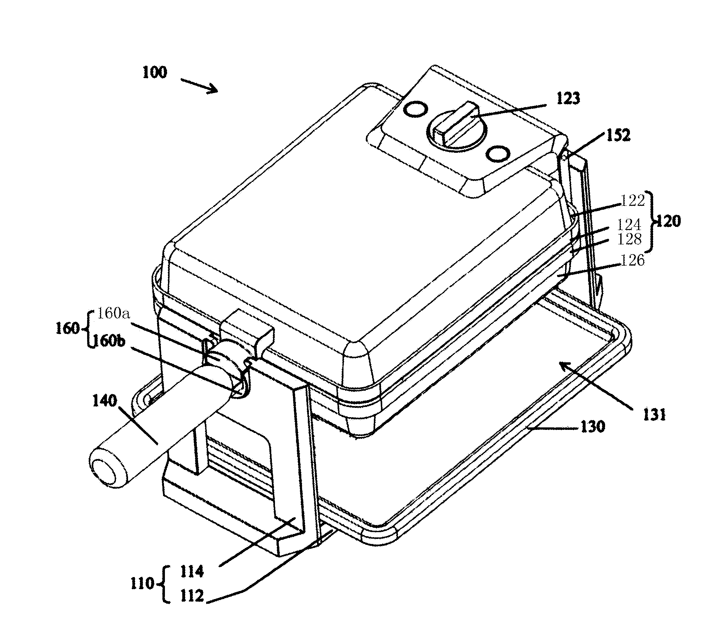
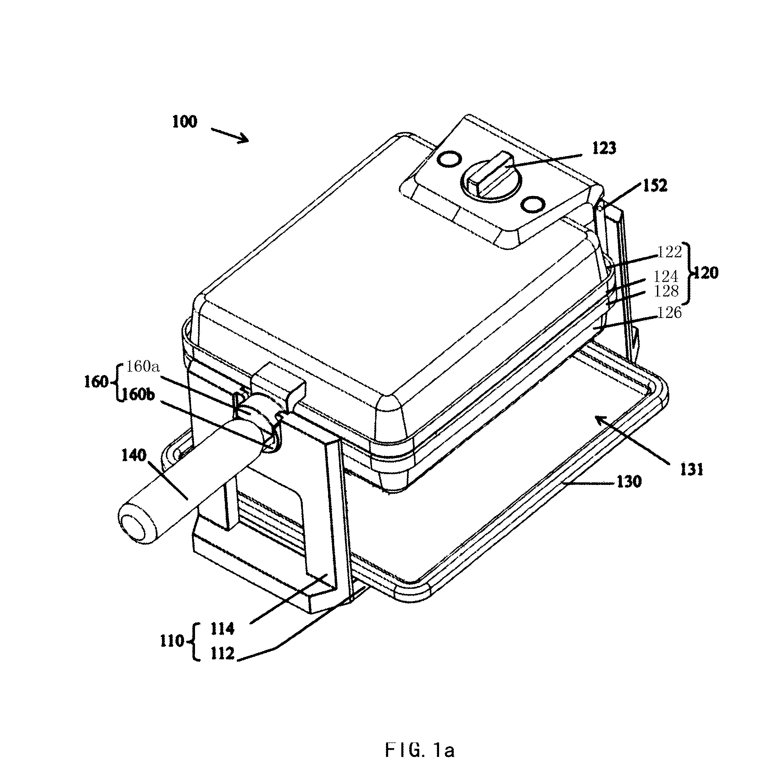
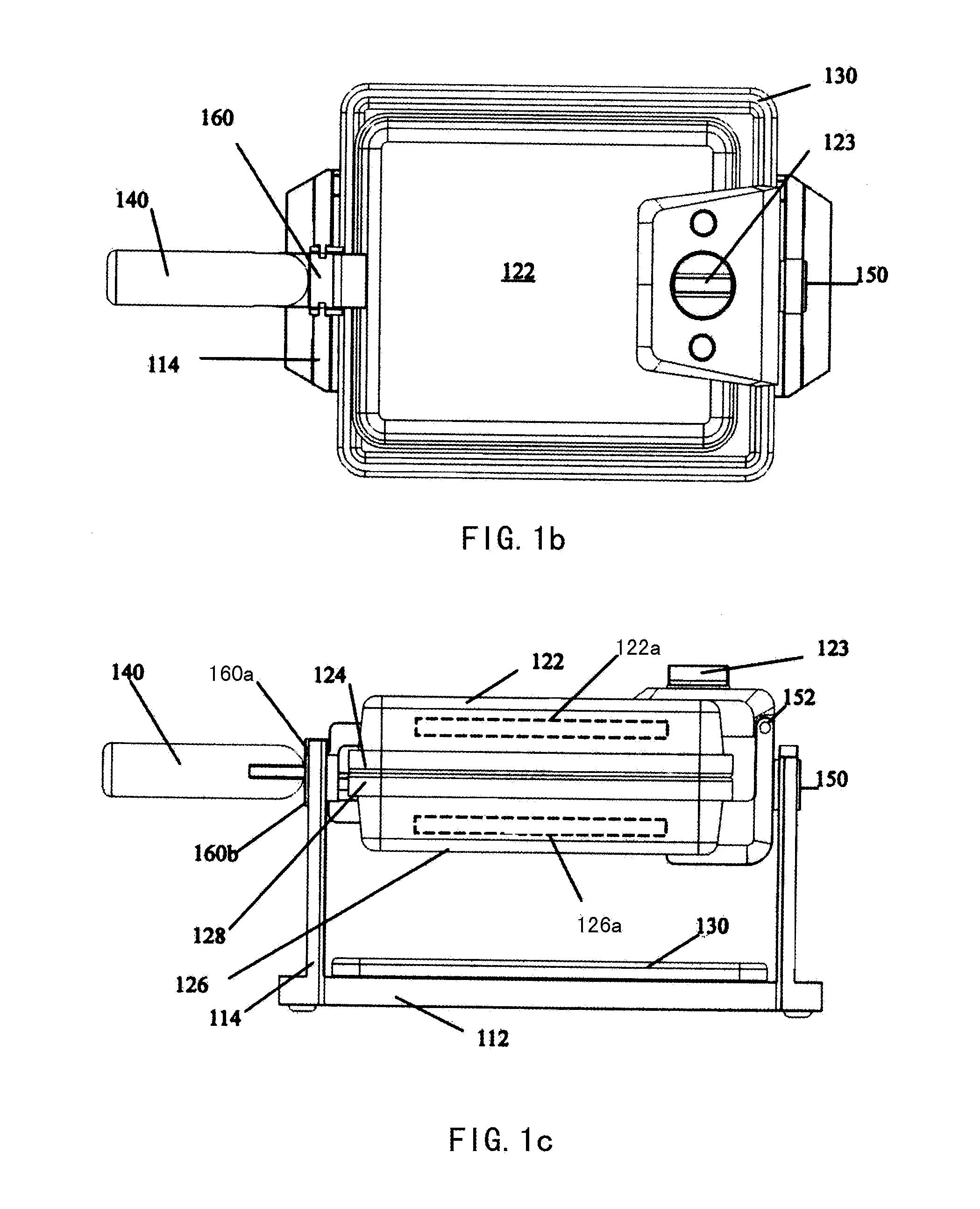
However, owing to the large load-bearing surface of the collecting plate (130), after the muffin maker completes its work, the collecting plate (130) takes up too much room and it is possible to lose the collecting plate (130) for storing it separately.
So it is inconvenient for users to store the collecting plate (130).

Method used


Image

  • Muffin baker
  • Muffin baker
  • Muffin baker

Examples


Embodiment Construction

[0028]Referring to FIG. 2A, FIG. 2B, FIG. 2C, FIG. 2D, FIG. 2E and FIG. 2F, the muffin maker 210 comprises a support device 210, a main body 220, a collecting plate 230 and a handle 240. In the embodiment, the support device 210 comprises a pedestal 212 and two support arms 214, and the pedestal 212 that is set up between the two support arms 214 which are in relative positions is connected to these support arms 214. However, the present invention is not limited in the embodiment, these support arms 214 could also be set up in the top surface 211 of the pedestal 212, as long as the normal line 215 of the support arms 214 is perpendicular to the normal line 213 of the pedestal 212. The main body 220 comprises an upper shell 222, an upper baking plate 224, a lower shell 226 and a lower baking plate 228. The upper baking plate 224 and a lower baking plate 228 are respectively connected to the upper shell 222 and the lower shell 226, which are both between these shells 222, 226. A heati...


PUM


Abstract

A muffin maker comprises a support device, a main body and a collecting plate. A pedestal of the support device includes a first inserted portion. Two support arms of the support device include a rotary device. The main body is used for baking muffin and is connected to the rotary device. The collecting plate is mounted on the pedestal of the support device and includes a second inserted portion. The second inserted portion is connected with the first inserted portion and the normal line of the collecting plate is perpendicular to the normal line of the pedestal.

Description

FIELD OF THE INVENTION[0001]The present invention relates to a muffin maker, especially relates to a muffin maker having an inserted structure which could store a collecting plate.BACKGROUND OF THE INVENTION[0002]Muffin maker which is used for baking muffin has been widely used in families. Please refer to FIG. 1A, FIG. 1B and FIG. 1C, which are respectively a three-dimension view, a top view and a side view of the conventional muffin maker (100). The conventional muffin maker (100) comprises a support device (110), a main body (220), a collecting plate (130) and a handle (140). The support device (110) comprises a pedestal (112) and two support arms (114). The main body (120) comprises an upper shell (122), an upper baking plate (124), a lower shell (126) and a lower baking plate (128). With a rotary device (150) and a rotating shaft (160), the main body (120) is supported by the support arms (114). A pivot component (115) in the rotary device is used to make the upper shell (122) ...

Claims


Application Information

Patent Timeline
IPC IPC(8): A23P1/00A47J36/00H05B3/68
CPCA47J37/0611
Inventor CHANG, SHUHUI
Owner TSANN KUEN ZHANGZHOU ENTERPRISE CO LTD
Learn More