Earphone device and sound generating apparatus equipped with the same
a technology of generating apparatus and earphone device, which is applied in the direction of deaf-aid sets, earpiece/earphone attachments, transducer details, etc., can solve the problems of difficult to attach the seesaw switch to the housing of the intra-concha type earphone device such as the canal type earphone devi
- Summary
- Abstract
- Description
- Claims
- Application Information
AI Technical Summary
Benefits of technology
Problems solved by technology
Method used
Image
Examples
first embodiment
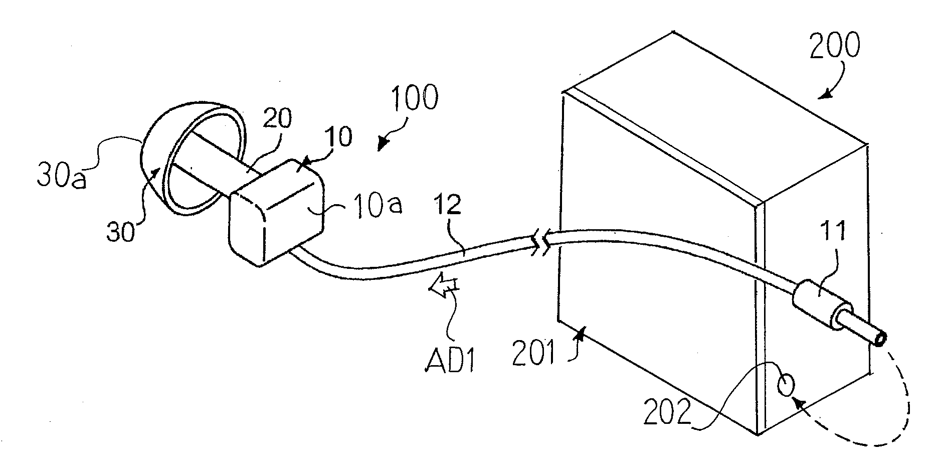
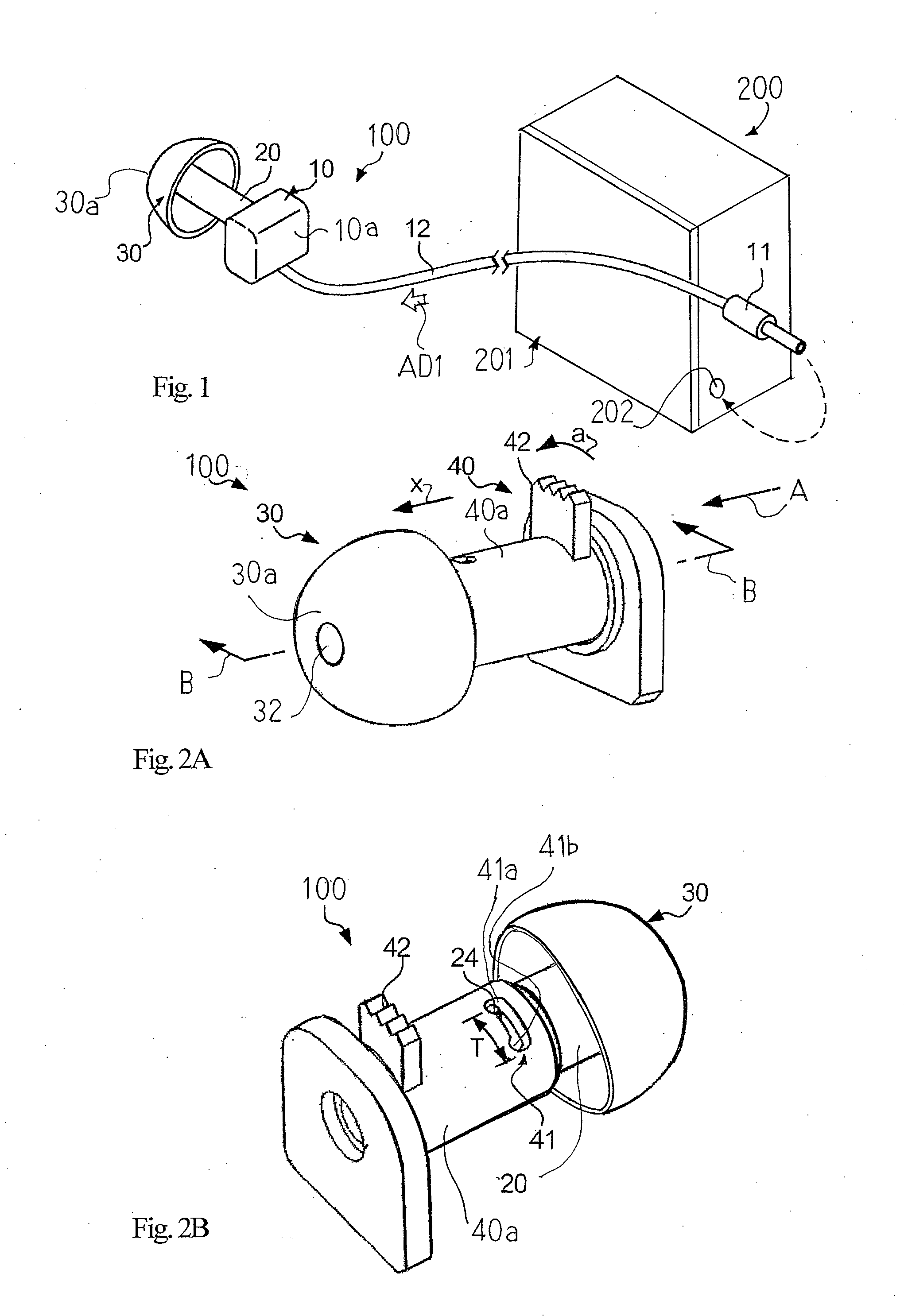
[0050]Referring first to FIGS. 1, 2A and 2B of the drawings, a sound generating apparatus 200 largely comprises an inserting type earphone device 100 and a compact disk player 201. The compact disk player 201 is well known to persons skilled in the art, and no further description is hereinafter incorporated for the sake of simplicity.
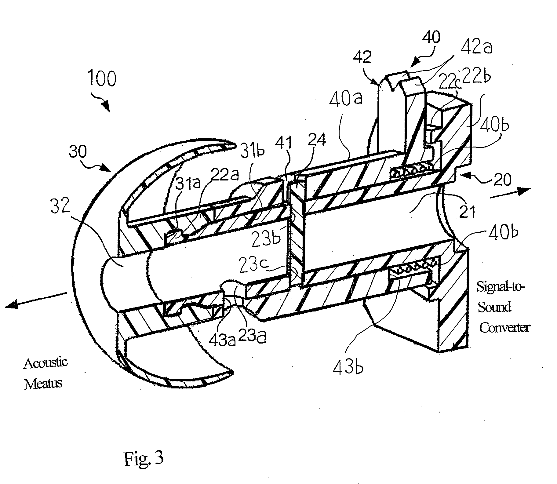
[0051]The inserting type earphone device 100 comprises a signal-to-sound converter 10, a jack 11, a lead cable 12, a sound tube 20, an ear pad 30 and a switching mechanism 40. The jack 11 is inserted into a socket 202, and an audio signal AD1 is supplied from the compact disk player 201 through the socket 202 to the jack 11 in playback on a compact disk. The lead cable 12 is flexible, and is connected between the jack 11 and the signal-to-sound converter 10. The audio signal AD1 is propagated through the lead cable 12 to the signal-to-sound converter 10.
[0052]The signal-to-sound converter 10 includes a casing 10a, a coil unit (not shown) and a diaphragm...
second embodiment
[0073]Turning to FIGS. 6A, 6B, 7A and 7B of the drawings, another inserting type earphone device 100A embodying the present invention largely comprises a signal-to-sound converter 10A, a sound tube 20A, an ear pad 30A and a switching mechanism 40A. The signal-to-sound converter 10A and ear pad 30A are similar in structure and material to the signal-to-sound converter 10 and ear pad 30. For this reason, description on the signal-to-sound converter 10A and ear pad 30A is omitted for the sake of simplicity.
[0074]The sound tube 20A is different from the sound tube 20 in that the circular holes 23b and 23c are not formed in the sound tube 20A. The other portions and holes of sound tube 20A are same as those of the sound tube 20, and are labeled with references designating the corresponding portions and hole of the sound tube 20 without detailed description.
[0075]The switching mechanism 40A includes a short tube 40Aa and a knob 42A. The stopper pin 24 and coil spring 40b are not incorpora...
third embodiment
[0082]Turning to FIGS. 8A and 8B of the drawings, yet inserting type another earphone device 100B embodying the present invention largely comprises a signal-to-sound converter 10B, a sound tube 20B, an ear pad 30B and a switching mechanism 40B. In this instance, the switching mechanism 40B is provided inside the sound tube 20B.
[0083]The signal-to-sound converter 10B includes a casing 10Ba, a voice coil 10Bb and a diaphragm 10Bc, and the voice coil 10Bb and diaphragm 10Bc is housed in the casing 10Ba. While the audio signal is flowing through the voice coil 10Bb, the diaphragm 10Bc vibrates, and the inside sound is generated.
[0084]The sound tube 20B has a tubular configuration. However, the sound tube 20B partially bulges out so that a wide chamber 211b takes place between narrow conduits 212b. The wide chamber 211b and narrow conduits 212b as a whole constitute a sound propagation hole 21B. The sound tube 20B is formed with a long hole 23Ba, and the long hole 23Ba extends in a direc...
PUM
 Abstract
Description
Claims
Application Information
 - R&D
- Intellectual Property
- Life Sciences
- Materials
- Tech Scout
- Unparalleled Data Quality
- Higher Quality Content
- 60% Fewer Hallucinations
Browse by: Latest US Patents, China's latest patents, Technical Efficacy Thesaurus, Application Domain, Technology Topic, Popular Technical Reports.
© 2025 PatSnap. All rights reserved.Legal|Privacy policy|Modern Slavery Act Transparency Statement|Sitemap|About US| Contact US: help@patsnap.com


