
Accessories cabinet

a cabinet and accessory technology, applied in the field of cabinets, can solve the problems of high-end closet system installation, limited access to only one side of the panel, and inability to achieve the esthetics that are desirable, and achieve the effect of convenient movemen

Inactive Publication Date: 2010-04-29
REV A SHELF
View PDF28 Cites 11 Cited by
  • Summary
  • Abstract
  • Description
  • Claims
  • Application Information

AI Technical Summary

Benefits of technology

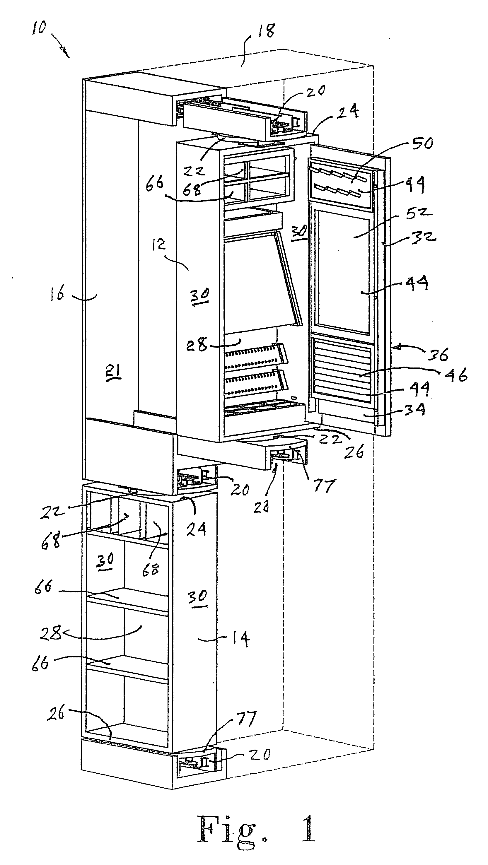
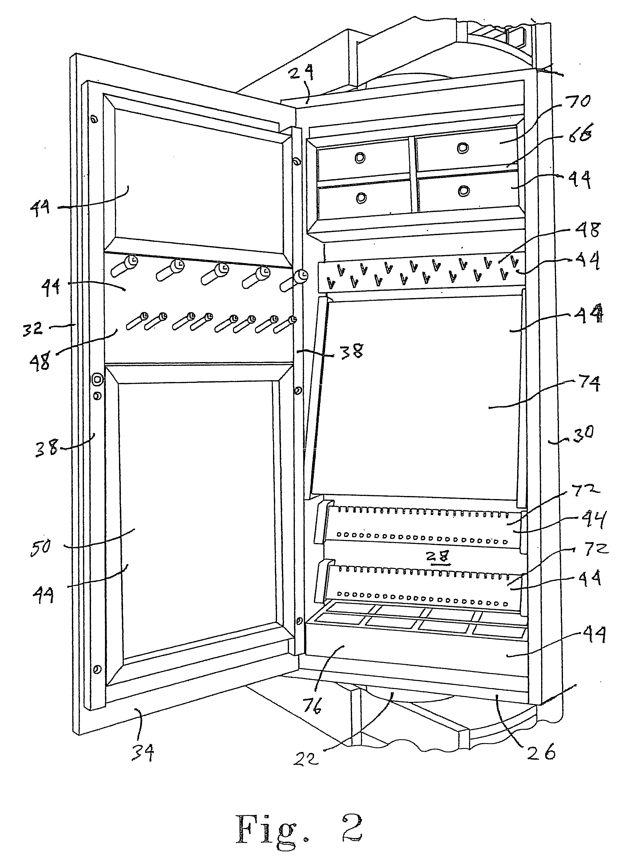
[0008]In another aspect, an accessories cabinet of the present invention can have a support, which can be secured in a closet at a desired location. A generally rectangular box can be included for displacement relative to the support. The box can have an upper end, a lower end, a back member extending between the upper and lower ends, and box sides extending between the box upper and lower ends, with the including at least one accessories support. A door having an interior surface and an exterior surface can be coupled to the box to move between an open position exposing the box interior and accessories support, and a shut position closing the box. Slide members can be coupled between the support and the generally rectangular box to facilitate linear movement of the box between a stored position inhibiting access to the box interior and a use position exposing the door for entry to the box interior. A pivot mechanism can be situated between the slide members and the generally rectangular box to permit rotation of the box from a storage alignment inline with the slides to a display alignment facilitating access to the box interior.
[0009]In yet another aspect, an accessories cabinet of the present invention can have a support, which can be secured in a closet at a desired location. Two or more generally rectangular boxes can be coupled to the support for independent displacement relative to the support. Each of the boxes can have an upper end, a lower end, a back member extending between the upper and lower ends, and box sides extending between the box upper and lower ends of each box. A door having an interior and exterior surface can be coupled to at least one of the boxes to independently move between an open position exposing the box interior and a shut position closing each box. Slide members can be coupled between the support and each of the generally rectangular boxes to facilitate independent linear movement of each box between a stored position inhibiting access to each box interior and a use position exposing any door of the box leading to entry to the box interior. A pivot mechanism can be situated between each of the slide members supporting a given rectangular box and each of the generally rectangular boxes coupled to the slide members to permit independent rotation of each box from a storage alignment with the slides to a display alignment facilitating access to the box interior.
[0012]In the various aspects of the present invention, an exterior surface of the door can include a handle facilitating the opening of the door. A cabinet face plate can be coupled to one of the box sides, the face plate having upper and lower ends that can extend above the box upper end and below the box lower end. The face plates can be dimensioned to form a substantially continuous surface with adjacent closet system faceplates when the accessories cabinet is situated in the stored position. The cabinet face plate can further include a handle facilitating movement of the box and slide members between the stored position and the use position.
[0013]In the various aspects of the present invention, the sides of each box can include a plurality of opposed openings directed to the box interior generally parallel to the back member. Additionally, a pair of vertical rails can be fixed to at least the interior surface of at least one of the doors, the rails including a plurality of opposed openings directed generally parallel to the door interior surface. A plurality of pair of pins can be received in selected opposed pairs of the plurality of openings. At least one accessories support can be situated within each cabinet, each accessory support having side portions, and each side portion can include an inclined slot coupled to one of the pairs of pins extending inward from either the box sides or the rails mixed to the doors. The accessories supports can be easily moved from one location to another.

Problems solved by technology

One difficulty with such slide-out panels is that access is generally limited to only one side of the panel, although access to the opposite side may be permitted by sliding the panel into the stored position, walking past the panel and then extending the panel outward.
While such a pegboard system provides the desired flexibility in the placement of the various supports and hangers, pegboard lacks the esthetics that is desirable, particularly in high end closet system installations.
There is therefore an unsatisfied need for an esthetically acceptable accessories cabinet that can be included in a high end closet system that can hold a substantial inventory of personal accessories and be supported to permit the cabinet to be easily moved from a storage position, where the contents is substantially inaccessible, to a use position, where the contents of the cabinet can be completely accessed without substantial movement of the person desiring access.

Method used


Image

  • Accessories cabinet
  • Accessories cabinet
  • Accessories cabinet

Examples


Embodiment Construction

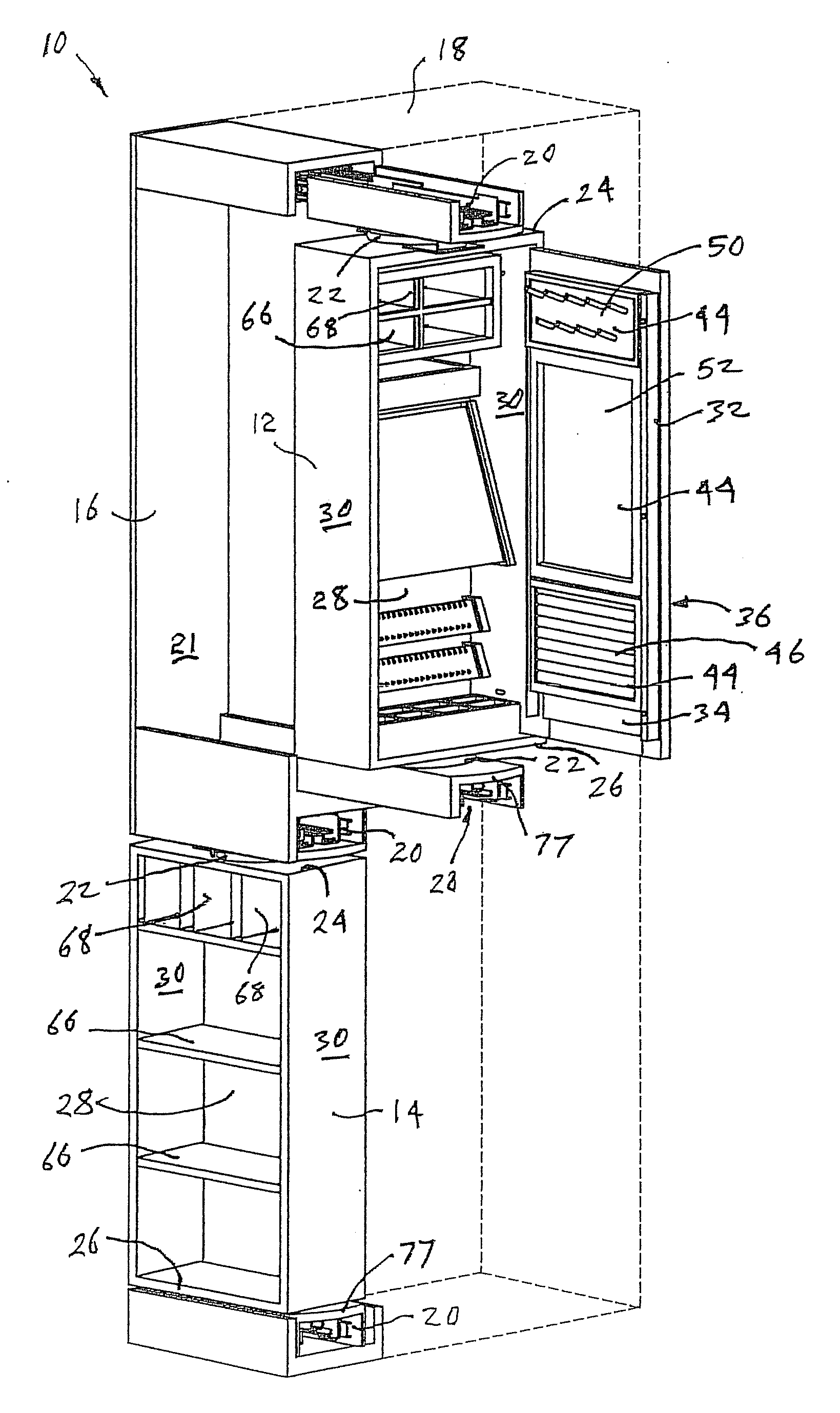
[0023]An accessories cabinet 10 is shown in FIG. 1 to include an upper box 12 and a lower box 14. The accessories cabinet 10 can consist of only a single box, which can be vertically elongated from that shown in FIG. 1. The accessories cabinet 10 can have a support 16, which can be secured in a closet at a desired location. In FIG. 1, the support 16 is shown to be position immediately adjacent to another unit 18 of a closet system, which is shown in phantom. The support 16 can be situated between two such other units 18. The support 16 can include a plurality of tracks 20 projecting outward from a rear surface 21 of the cabinet 10. Each of the upper box 12 and lower box 14 can be coupled to the tracks 20 for displacement relative to the support 16 between a storage position and a use position. The lower box 14 is shown in FIG. 1 in a stored position where the box 14 is recessed into the support 16 as far as possible. The upper box 12 is shown in FIG. 1 in a use position where the bo...


PUM


Abstract

A vertically oriented generally rectangular box with a hinged lid is pivotally supported on a pull-out slide permitting the box to be linearly displaced and rotated between a stored position and a use position. Two or more such boxes can be vertically stacked for independent movement and use. The box sides and rails on the door interior include opposed rows of holes accepting pins that are received in inclined slots in the sides of a plurality of accessories supports that can be selectively positioned within the box.

Description

BACKGROUND OF THE INVENTION[0001]1. Field of the Invention[0002]The present invention generally relates to cabinets suitable for use in domestic areas such as closets and dressing areas, and particularly to cabinets adapted to be installed in closet systems to hold personal accessories and supported to permit the cabinet to be easily moved from a storage position to a use position.[0003]2. Description of the Prior Art[0004]There are presently available any number of closet systems to assist one with the organization of clothing and accessories within a closet, particularly a walk-in closet. The closet systems often have a plurality of baskets or drawers, one or more series of shelves that may be vertically sub-divided, some areas having horizontal rods for receiving hangers, and so forth. Some closet systems include slide-out panels for organizing and storing various articles of clothing and accessories. The slide-out panels have the advantage of occupying only a small amount of wal...

Claims


Application Information

Patent Timeline
IPC IPC(8): A47B43/00A47B96/00
CPCA47B88/06A47B88/48
Inventor CHAMBERS, PAUL F.NOE, DAVID P.
Owner REV A SHELF
Learn More