Mattress retainer buckle

Active Publication Date: 2010-03-04
A H BEARD
View PDF7 Cites 17 Cited by
  • Summary
  • Abstract
  • Description
  • Claims
  • Application Information

AI Technical Summary

Benefits of technology

[0007]The present invention provides a mattress retainer suited for use with adjustable beds to constrain movement of a mattress relative to an adjustable mattress support when the mattress support is articulated to reposition various portions of the mattress. The mattress retainer is a two-piece snap-fit buckle, one piece of which is secured to the upper surface of the mattress supporting adjustable bed base and the other piece of which is secured to the underside of the mattress, such that the two-piece buckle is positioned between the mattress and the mattress support. When the buckle is closed or clamped shut, the mattress cannot shift on the mattress support as the adjustable mattress support or base is articulated to raise and / or lower various portions of the mattress. Because the buckle is relatively flat and positioned beneath the mattress, the buckle does not interfere with the comfort of persons sitting near the edge of the mattress or lying atop the mattress.
[0009]Preferably, the two pieces of the buckles are secured to a fabric strap, which strap is attached to the underside of the mattress and the top side of the bed base with the straps and buckles being so positioned that the mattress may be reversed end-for-end so as to accommodate extended life and use of the mattress.

Problems solved by technology

Besides detracting from the aesthetic appearance of the bed, this type of mattress retainer also creates a barrier at the foot of the bed which may be uncomfortable to persons who are sitting on the edge of the mattress.
Furthermore, there is a problem with this type of mattress retainer when used on a retail store display.
When so used and displayed and while demonstrating the adjustable bed to a potential consumer, if both the head and foot ends of the bed are raised, the mattress lifts up in the air off of the center section of the bed, thereby presenting an unsightly and unprofessional product.
But this type of retainer is subject to tearing of the edge of the mattress if a person resting or seated atop the mattress applies exclusive force, causing movement of the mattress on the adjustable bed base.
This type of retainer is physically difficult to use or apply because it is necessary to bend the mattress so that the edges of the sleeve or sleeves on the underside of the mattress fit into the clips on the bed base.
Furthermore, this type of retainer may also be subject to tearing of the underside of the mattress if excessive force is applied to move the mattress on the bed base.

Method used


Image

  • Mattress retainer buckle
  • Mattress retainer buckle
  • Mattress retainer buckle

Examples


Embodiment Construction

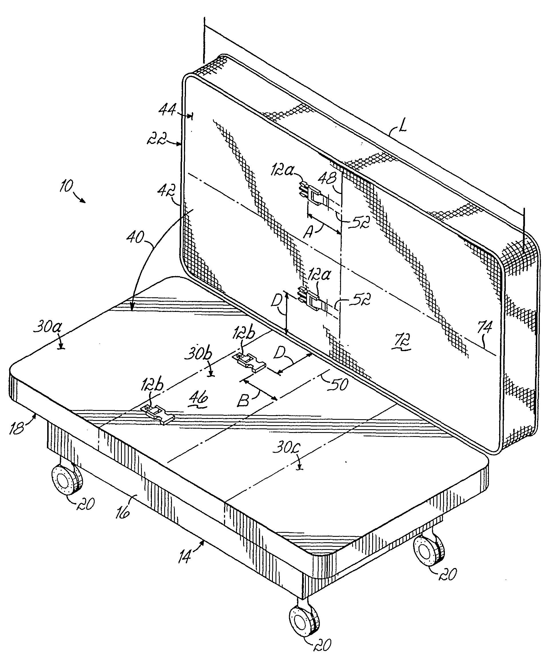
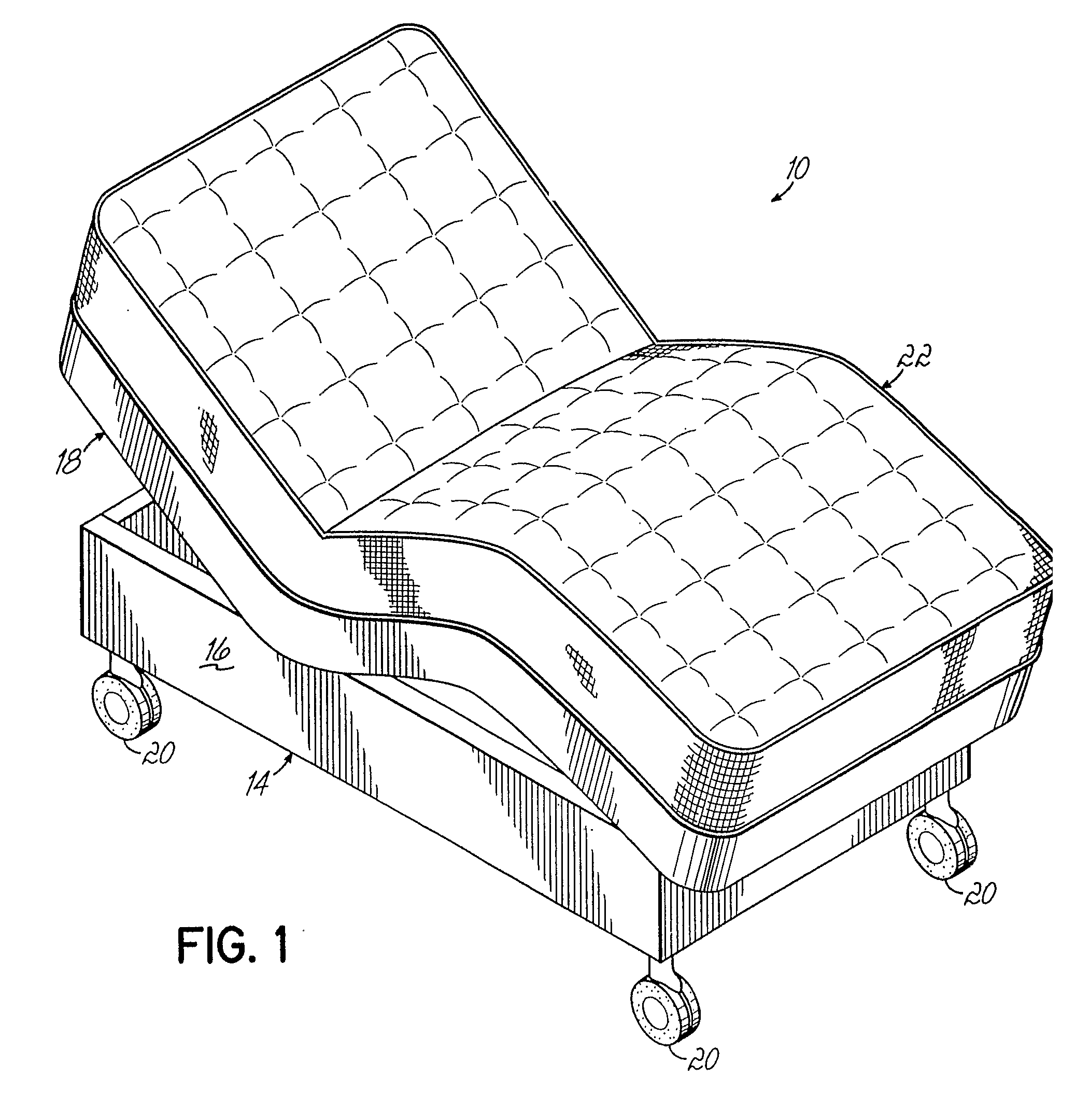
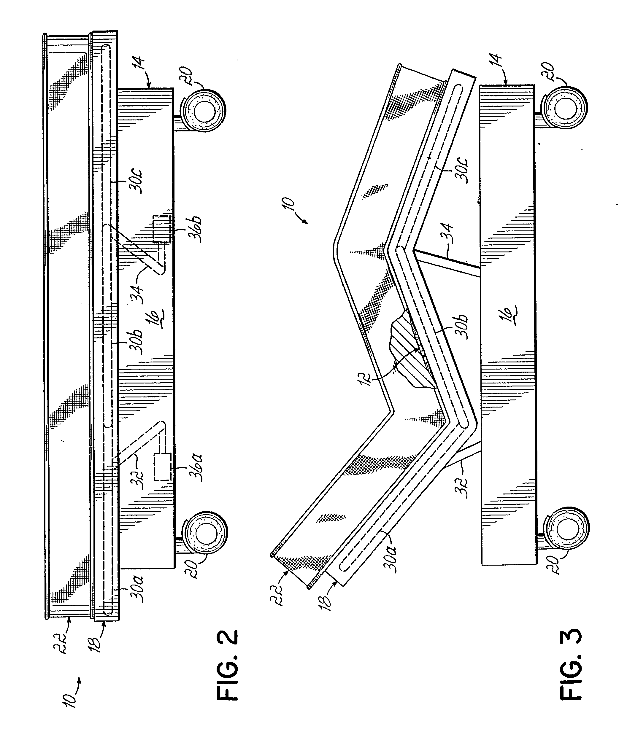
[0017]Referring to FIGS. 12 and 3, there is shown a typical adjustable bed 10 of the type with which the mattress buckle retainers 12 (FIGS. 3, 4, 5 and 6) according to this invention may be utilized. The adjustable bed 10 comprises a bed frame 14 including a base 16 and an adjustable mattress support 18 disposed on an upper portion of the base 16. Casters 20 may be provided on the base 16 to facilitate repositioning the adjustable bed 10 within a room. A conventional adjustable mattress 22 is disposed on the mattress support 18.

[0018]With particular reference to FIG. 4, it will be seen that a pair of mattress retainer buckles 12 are disposed on opposite longitudinal sides of the mattress support 18 and the mattress 22 such that the mattress retainers 12 reside between the mattress support 18 and the mattress 22 when the mattress is atop the support. The mattress retainer buckles 12 each comprise a snap-fit male section or component 12a attached to the underside of the mattress and ...


PUM


Abstract

A mattress buckle for securing the position of a mattress (22) on the base (16) of an adjustable bed (10). The mattress comprises one of a pair of male and female elements of the buckle (12) secured to an upper surface of the bed base (16) and the other of the pair of male and female elements of the buckle (12) secured to the underside of the mattress (22). When these elements of the buckle are interlocked in snap-fit engagement, the mattress is constrained against movement on the base as the adjustable panels of the bed base are articulated relative to one another through various positions of adjustment.

Description

FIELD OF THE INVENTION[0001]The present invention pertains generally to bedding systems, and more particularly, to a retainer for maintaining the position of a mattress on an adjustable bed.BACKGROUND OF THE INVENTION[0002]Adjustable beds are known in the art and provide improved comfort to persons resting thereon by permitting various portions of the sleeping surface to be selectively adjusted to different positions. Generally, these adjustable beds comprise a mattress supported on a bed frame having an adjustable mattress support. The mattress support includes one or more adjustable panels, and typically, between about three and five adjustable panels. The adjustable panels are movable from a horizontal position to permit various portions of the mattress to be raised and / or lowered to thereby provide a comfortable position for persons reclining thereon. The adjustable panels may be moved by manual manipulation of individual panels, by hand cranks, or more typically, by linkages ac...

Claims


Application Information

Patent Timeline
IPC IPC(8): A47C19/02A47C17/86
CPCA47C21/026A47C19/02
Inventor BEARD, ALLYNLONGMAN, PAUL
Owner A H BEARD
Why Eureka
Try Eureka