
Method and apparatus for testing for the presence of excess drivers in a surgical cartridge

a technology for detecting the presence of excess drivers and cartridges, which is applied in the direction of surgery, structural/machine measurement, medical science, etc., can solve the problems of difficult to determine whether too many or too few drivers are placed in a particular aperture, labor-intensive task of inserting drivers into cartridges, and severe danger to patients

Active Publication Date: 2009-11-12
SCHNIPKE FAMILY LIABILITY
View PDF5 Cites 264 Cited by
  • Summary
  • Abstract
  • Description
  • Claims
  • Application Information

AI Technical Summary

Benefits of technology

"The invention is a device and method for testing surgical cartridges with slots and drivers. The device includes a base, a carriage, a prime mover, and a tooling plate with blades. The blades are inserted into the cartridge slots and displaced along a horizontal path. The device detects any excess drivers and records the movement of the tooling plate relative to the carriage. The technical effect of the invention is to provide a reliable and efficient method for testing surgical cartridges."

Problems solved by technology

The task of inserting the drivers into the cartridge is labor-intensive due to the small size and number of the drivers and the apertures.
While the latter results in harm due to a staple not being driven at one region of the incision, the former results in a jammed instrument, thereby creating a severe danger to the patient.
It is extremely difficult to determine whether too many or too few drivers are placed in a particular aperture, because of the relative size of the apertures and the drivers.
There is, however, no way known to Applicants to rapidly and conveniently test a cartridge to determine if it has precisely the correct number of drivers in each aperture.

Method used


Image

  • Method and apparatus for testing for the presence of excess drivers in a surgical cartridge
  • Method and apparatus for testing for the presence of excess drivers in a surgical cartridge
  • Method and apparatus for testing for the presence of excess drivers in a surgical cartridge

Examples


Embodiment Construction

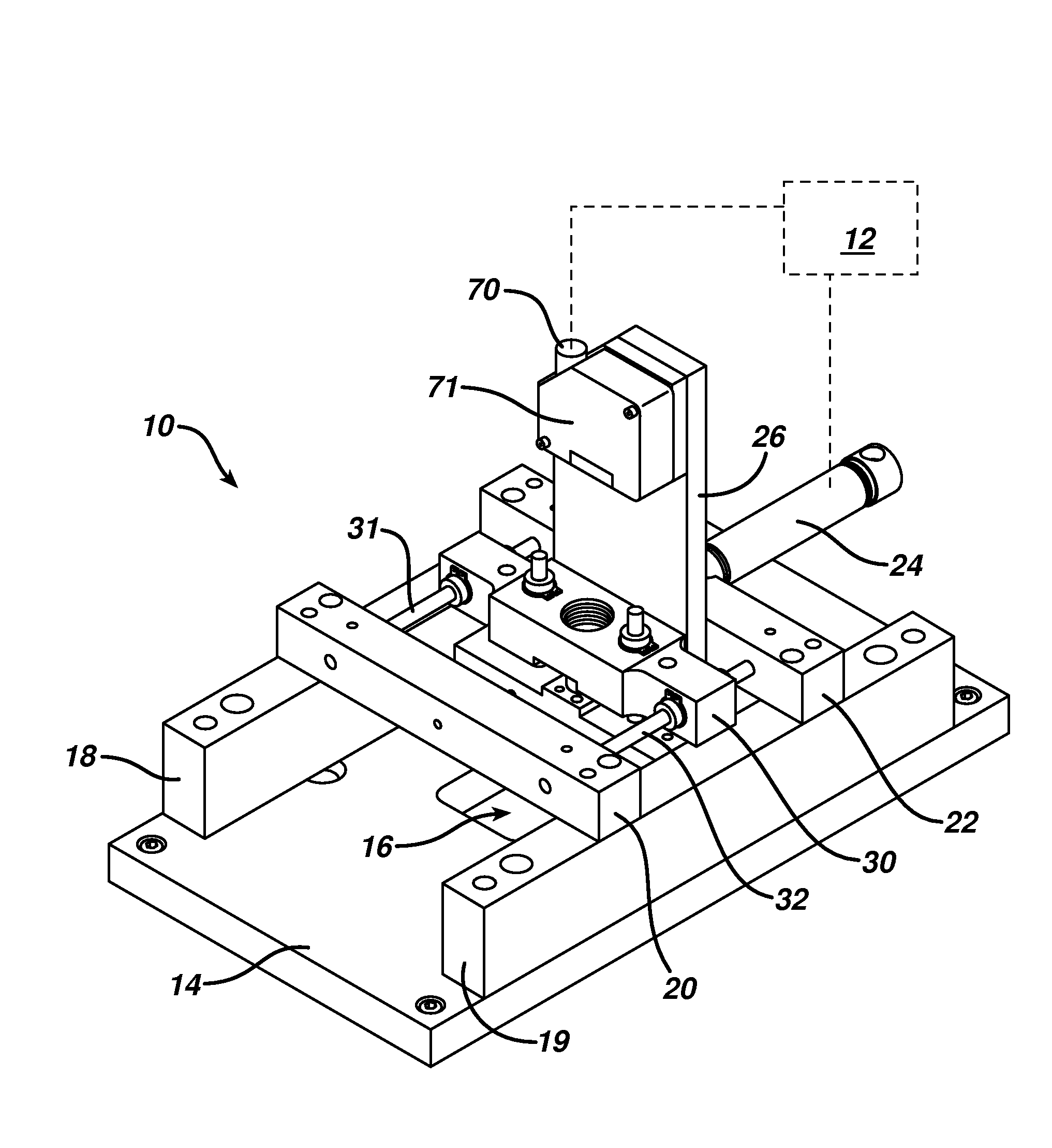
[0024]The testing apparatus 10 shown in FIG. 2 is preferably positioned along an assembly line in which cartridges, such as that shown in FIG. 1, are assembled. Preferably, cartridges are mounted in pallets, as described in U.S. Pat. No. 6,990,796 to Schnipke, et al., which is incorporated herein by reference, and moved along an assembly line by a conveyor belt, as is known in the art. Such cartridges are fitted with drivers, one or more springs and other components during the assembly process. After complete assembly, or preferably nearly complete assembly, the cartridge is tested by the testing apparatus 10 in order to determine whether more than the required number of drivers has been inserted into the apertures of the cartridge. After testing, the cartridge is then designated, such as by recording the results of the test in the memory of a central computer 12, as either acceptable if it passed the test, or defective if it failed. This designation is then used to determine subseq...


PUM


Abstract

A testing method and apparatus for determining whether surgical cartridges have excess drivers. A blade is disposed in the slots of the cartridge and displaced while it contacts the floor of the slot. If an excess driver is encountered, the blade is displaced away from the floor and this movement is detected, preferably by an electronic sensor. The apparatus includes a base plate to which a carriage is mounted, either directly or through other structural members. The carriage is configured to slide along a pair of parallel shafts, and is driven by a pneumatic ram or other linear prime mover. A tooling plate is moveably mounted to the carriage, and the blade is mounted to the tooling plate. Movement by the blade due to excess drivers results in movement by the tooling plate relative to the carriage, which is detected and recorded, such as by a computer.

Description

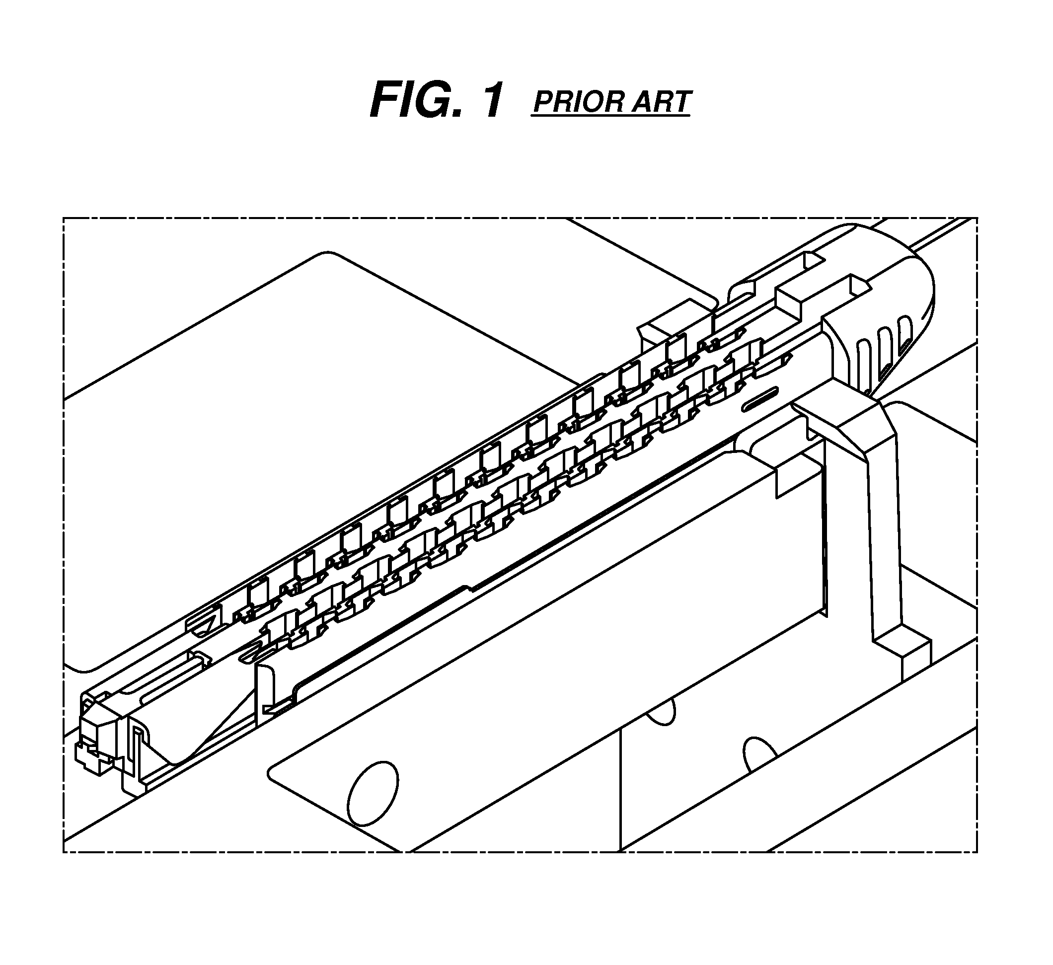
(e) BACKGROUND OF THE INVENTION[0001]1. Field of the Invention[0002]This invention relates generally to an apparatus and a method for testing surgical cartridges into which discrete articles have been inserted, and more particularly for testing whether there are too many discrete articles in a surgical stapling cartridge.[0003]2. Description of the Related Art[0004]In the field of microsurgery, a surgical instrument having a cutting blade traverses a specific path through tissue. One feature of the surgical instrument is a single-use cartridge, shown in FIG. 1, that is a holder for surgical staples. The cartridge is an elongated plastic body with a longitudinal channel that serves as a guide for a surgical blade. The cartridge has rows of small staples on opposite sides of the channel, and these rows are aligned parallel to the guide channel. Drivers are inserted in apertures (also called “pockets”) aligned with the rows in order to push the staples out of the cartridge and through ...

Claims


Application Information

Patent Timeline
Patent Type & Authority Applications(United States)
IPC IPC(8): G01M19/00G01M99/00
CPCA61B17/07207A61B2017/00725A61B2017/00526A61B2017/07278A61B2017/07271
Inventor DOEPKER, BRIAN T.ERHART, DAVID B.
Owner SCHNIPKE FAMILY LIABILITY
Learn More