
Dive belt

a technology of diving belt and diving ring, which is applied in the field of diving belt to achieve the effects of quick and easy drop, increased mobility of the diver, and quick and easy drop

Inactive Publication Date: 2009-06-11
TREBOR IND
View PDF33 Cites 2 Cited by
  • Summary
  • Abstract
  • Description
  • Claims
  • Application Information

AI Technical Summary

Benefits of technology

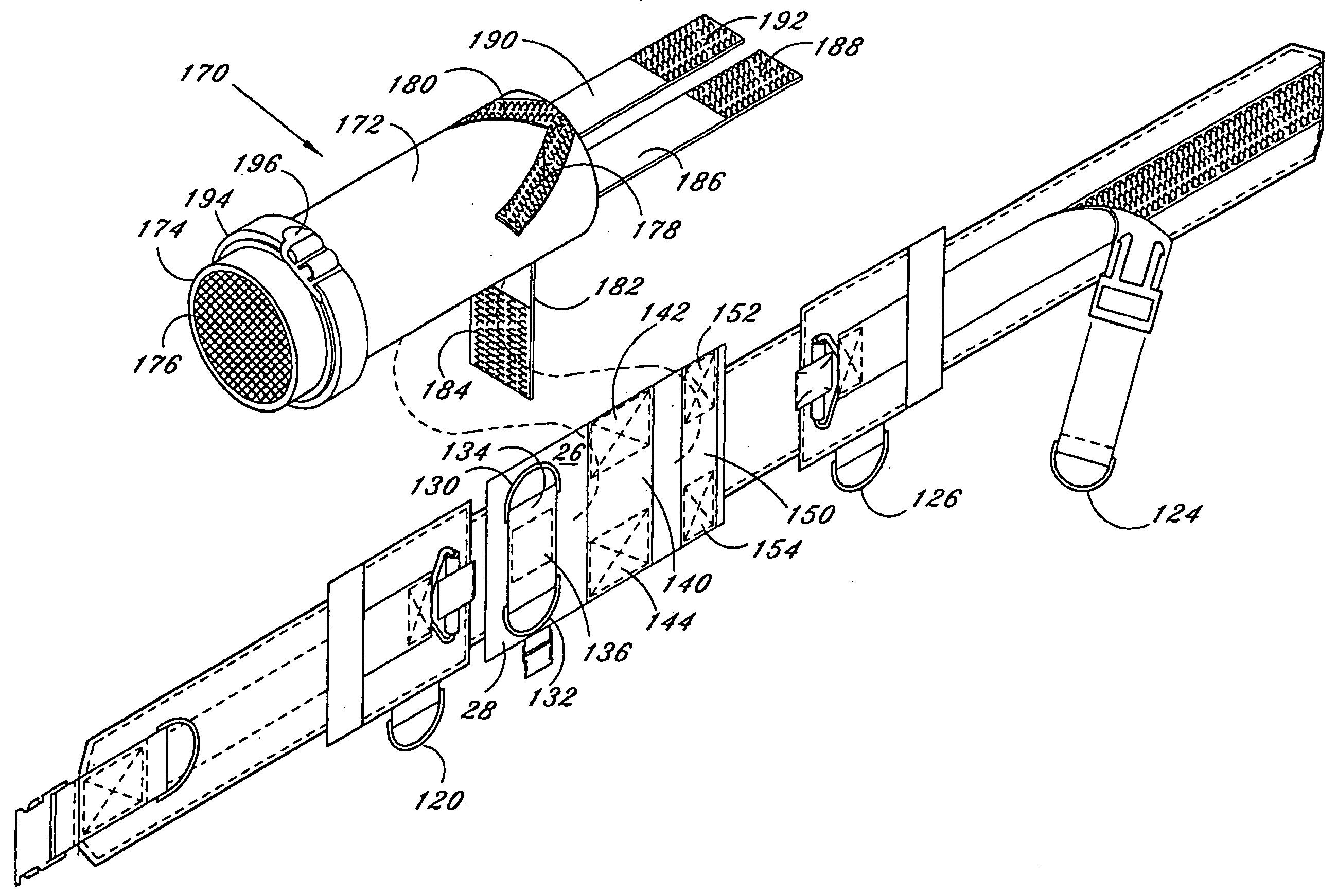
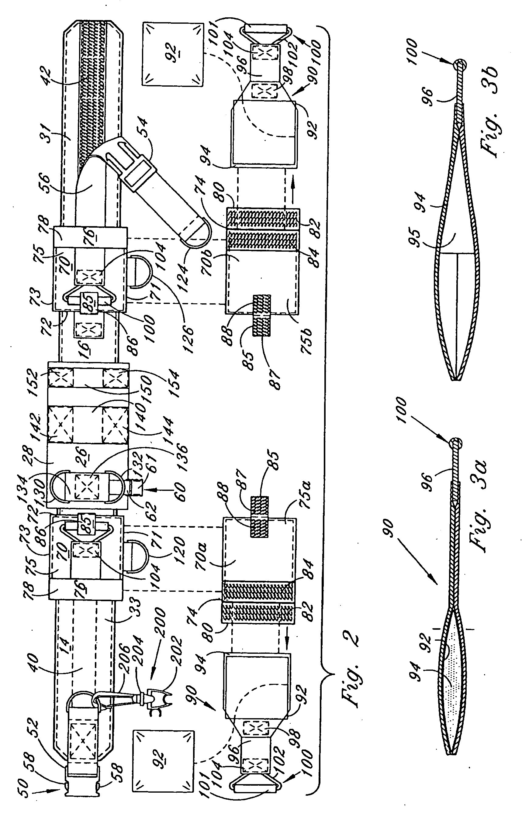
[0016]The present invention generally discloses a dive belt constructed for quick removal of preferably a pair of weights, associated with the belt, in the event of an emergency. The belt remains in place and is not discarded as the weights are quickly and easily dropped. Thus, a diver can access the surface quickly, without worrying about the typical problems associated with dropping the entire weight belt. The invention also allows the weights to be dropped by the simple procedure of pulling a rip cord to free the weight contained in a pouch which is normally housed within a pocket secured to the belt. The invention further allows the attachment of a supplemental air supply system. The air supply system is positioned on the belt, horizontally across the diver's back such that a standard dive tank could be worn in conjunction with the supplemental air system. This mounting configuration of the supplemental air system has the advantage of greater mobility for the diver when wearing the present invention.

Problems solved by technology

This configuration suffers the problem of the hose tugging directly on the mouthpiece being utilized by the diver.

Method used


Image

  • Dive belt
  • Dive belt
  • Dive belt

Examples


first embodiment

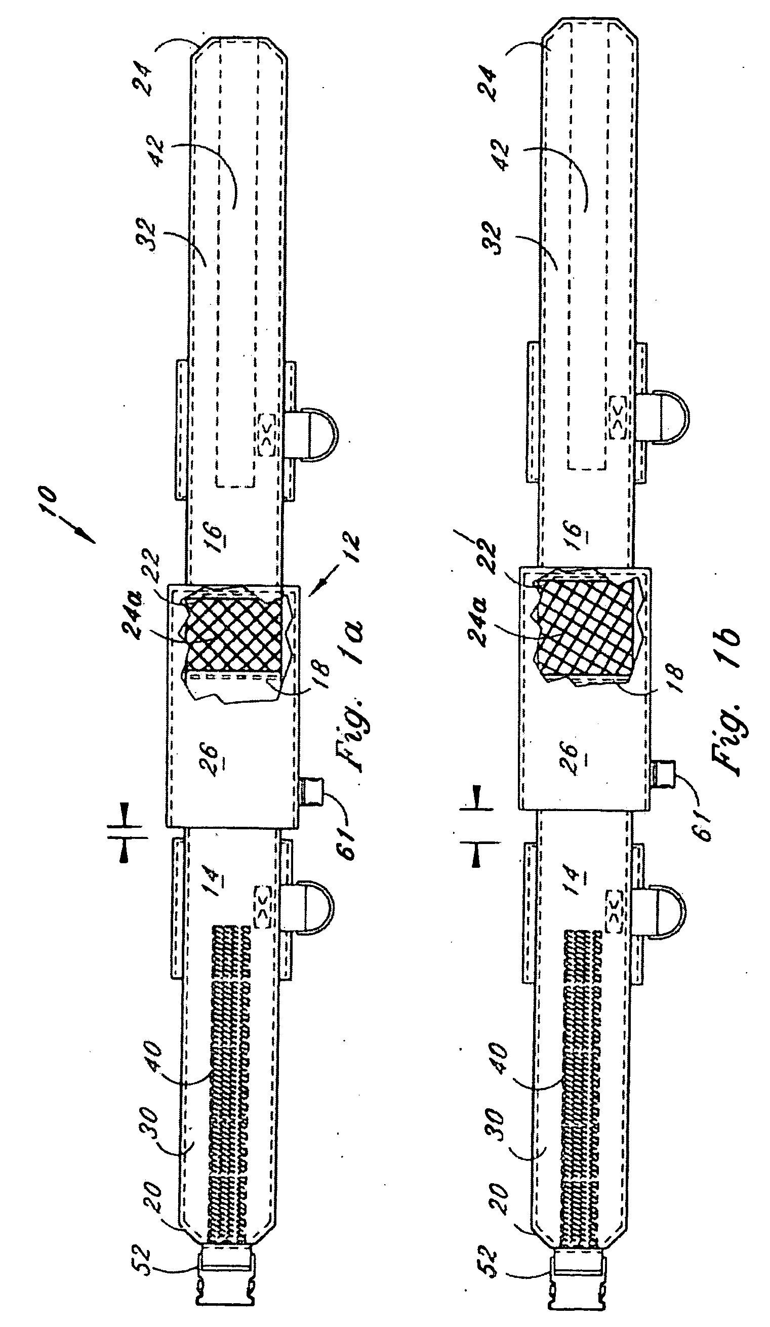
[0064]As seen in FIGS. 1 through 4, the removable weights dive belt is generally shown at 10. Belt member 10 includes a body member 12 having a first main section 14 and a second main section 16. First section 14 includes a hidden first end 18 and an exposed second end 20, while second section 16 includes a hidden first end 22 and an exposed second end 24.

[0065]Hidden first ends 18 and 22 are conventionally attached to respective ends of an elastic section 24 so that elastic section 24 is interposed between sections 14 and 16. Sections 14 and 16 and elastic section 24 are collinear and form or define the circumference of dive belt 10, when wrapped around a diver's waist when in use. Hidden first ends 18 and 22 and elastic section 24 are disposed within a sleeve member 26. Sections 14 and 16 and sleeve member 26 can be constructed from conventional materials commonly used in making dive belts.

[0066]End 22 is also attached to an adjacent portion of sleeve member 26 by conventional mea...

second embodiment

[0081]FIGS. 5a through 5e illustrate a second embodiment body member for dive belt 10. In this embodiment, an adjustable body member 300 which includes a fixed section 316, adjustable and removable section 400, attachment section 336 and an elastic member 324 which is disposed within attachment section 336, when belt 10 is properly constructed.

[0082]As seen in FIG. 5a adjustable section 400 has a first end 404 and a second end 406. A first hook and loop fastening means 410 and a second hook and loop fastening means 408 are disposed on a first surface 402 of adjustable section 400. (In lieu of second hook and loop fastening means 408, first hook and loop fastening means 410 can be extended along substantially the entire length of first surface 402 of adjustable section 400, see FIG. 8). Padding can be provided within at least the portion of adjustable section 400 which is adjacent first hook and loop fastening means 410 (FIG. 5a). Furthermore, the portion of adjustable section 400 wh...


PUM


Abstract

A dive belt is provided for use by divers during underwater activities, such as scuba diving. The belt comprises a body member and a weight release system which is quickly removal while the belt remains in place on the diver. A tow clip can be attached to the belt and may be used in conjunction with a surface air supply system for pulling the surface air supply system.

Description

[0001]This application is a continuation of U.S. application Ser. No. 11 / 108,354, filed Apr. 18, 2005, which is a continuation of U.S. application Ser. No. 10 / 055,678, filed Jan. 23, 2002, now U.S. Pat. No. 6,881,011, which is a continuation-in-part of U.S. application Ser. No. 09 / 687,889, filed Oct. 13, 2000, now U.S. Pat. No. 6,712,557, issued Mar. 30, 2004, which is a continuation of application Ser. No. 09 / 071,583, filed May 1, 1998, now U.S. Pat. No. 6,132,142, issued Oct. 17, 2000, which is a continuation of application Ser. No. 08 / 560,329, filed Nov. 17, 1995, now U.S. Pat. No. 5,746,542, issued May 5, 1998, all incorporated by reference.BACKGROUND OF THE INVENTION[0002]1. Field of the Invention[0003]The present invention relates generally to diving in which a variety of body sizes and shapes challenge gear manufactures to comfortably and safely provide weight belts, buoyancy compensators, and garments for. The same is true for a wide range of outdoor enthusiast and workers n...

Claims


Application Information

Patent Timeline
Patent Type & Authority Applications(United States)
IPC IPC(8): B63C11/30B63C11/08
CPCB63C11/30Y10S224/934B63C2011/306
Inventor CARMICHAEL, ROBERT MANUEL
Owner TREBOR IND
Learn More