Floating mount bottom plate holder in a glassware forming machine

a technology bottom plate, which is applied in the field of glassware forming machine, can solve the problems of prone to fracture, leakage of cooling wind to the vacuum passage in the mounting base, and large unsupported seal carried by the outer ring

Inactive Publication Date: 2008-12-18
OWENS-BROCKWAY GLASS CONTAINER INC
View PDF7 Cites 27 Cited by
  • Summary
  • Abstract
  • Description
  • Claims
  • Application Information

AI Technical Summary

Problems solved by technology

An absence of adequate sealing between the spud and its mounting base, and between the spud and the bottom plate, results in leakage of cooling wind to the vacuum passage in the mounting base.
Furthermore, fixed mounting of the outer ring on the base necessitates a fairly large annular gap between the outer ring and the opposing surface of the annular recess in the bottom plate, so that the seal carried by the outer ring is largely unsupported and prone to fracture when installing the bottom plate over the outer ring.

Method used


Image

  • Floating mount bottom plate holder in a glassware forming machine
  • Floating mount bottom plate holder in a glassware forming machine
  • Floating mount bottom plate holder in a glassware forming machine

Examples


Embodiment Construction

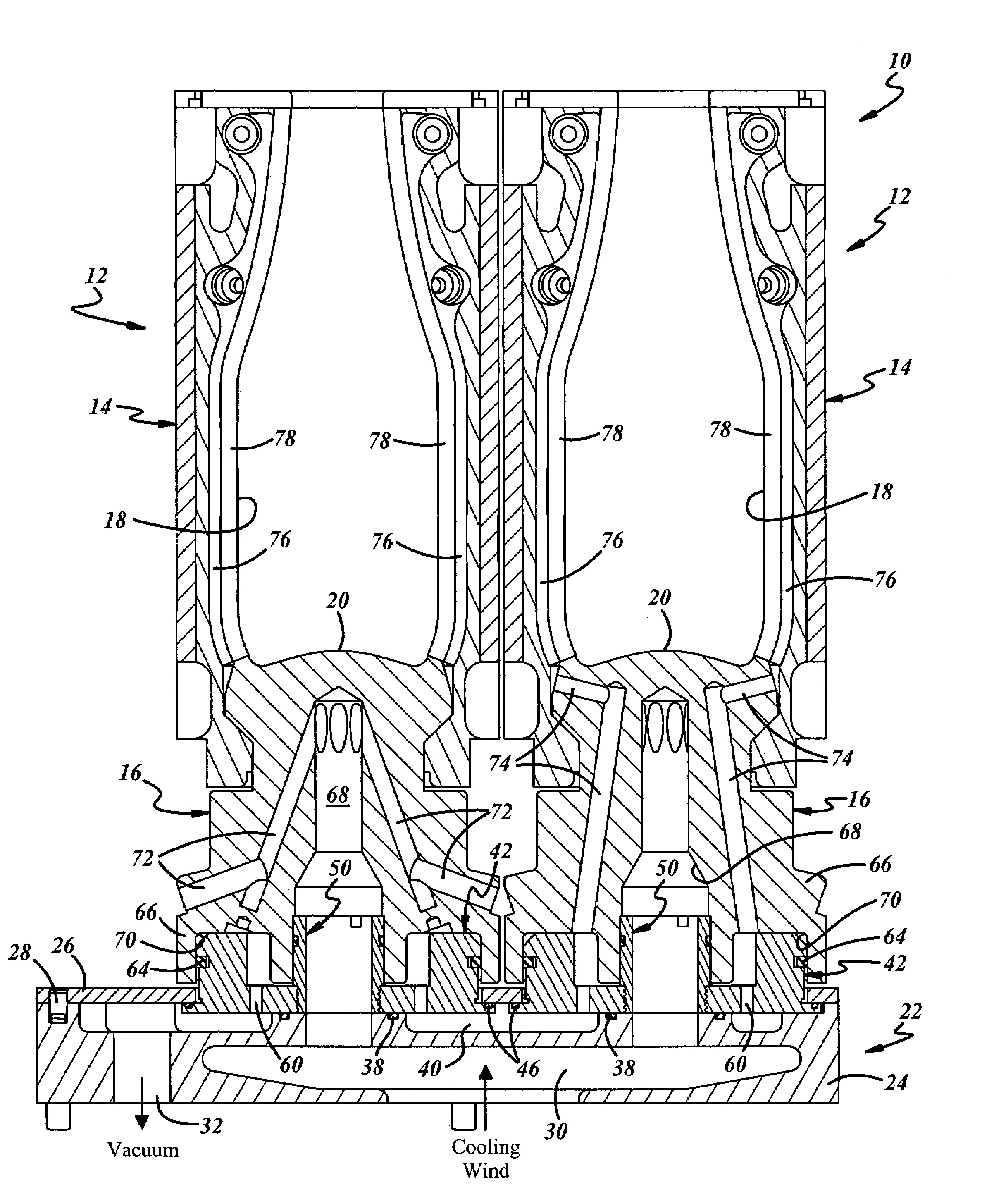
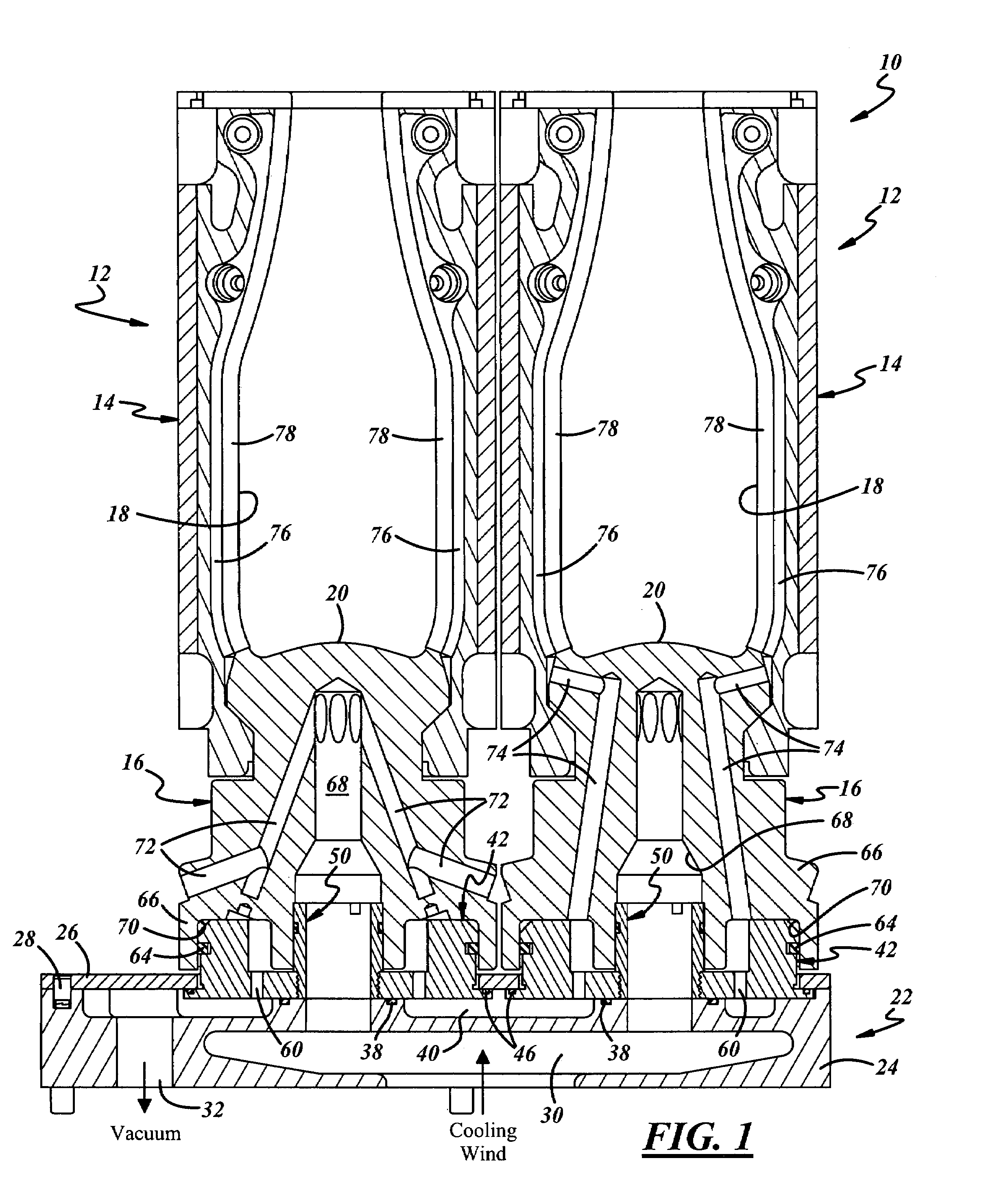
[0010]FIGS. 1, 3 and 4 illustrate a portion of an exemplary blow station in a glassware forming machine 10. The illustrated exemplary embodiment includes a pair of blow molds 12, although a greater or lesser number of blow molds could be provided. Each blow mold 12 includes a pair of blow mold sections or halves 14 closable around a bottom plate 16 to form a blow mold cavity 18. The upper surface 20 of bottom plate 16 thus forms the blow mold surface against which the base or bottom of the glassware article is molded. Blow mold halves or sections 14 typically are mounted for opening and closing movement with respect to bottom plates 16 to open and close the blow mold cavities. Bottom plates 16 are relatively stationary, although there is a limited “float” for each bottom plate to accommodate closing of the blow mold halves. Blow molds 12 are illustrated in the closed position in FIGS. 1, 3 and 4.

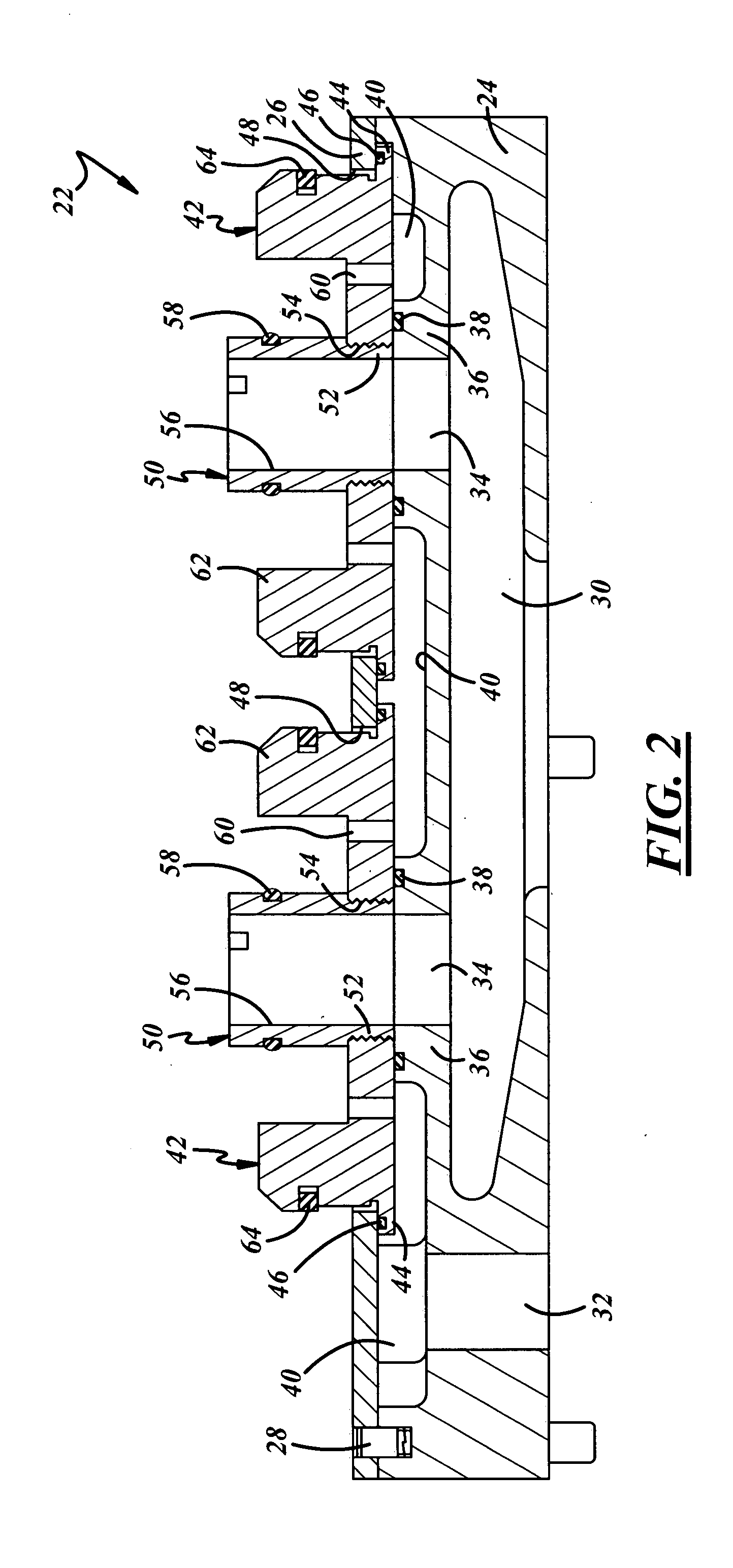
[0011]Bottom plate 16 is mounted on a bottom plate mounting assembly 22. Assembly 22 inc...


PUM

PropertyMeasurementUnit
vacuumaaaaaaaaaa

Abstract

A glassware mold bottom plate mounting arrangement in a glassware forming machine includes a floating ring captured by a cap plate on a base for limited lateral movement with respect to the base and the cap plate. A hollow spud is rigidly secured to and extends from the ring. A cooling wind passage in the base opens through the hollow spud, and a vacuum passage in the base opens through the ring at a position spaced from the spud. A glassware mold bottom plate is removably telescopically received over the ring and the spud. The bottom plate has a central air passage received over the spud, an annular recess received over the ring, and a peripheral air passage that opens into the annular recess such that the central and peripheral air passages open to the cooling wind and vacuum passages in the base through the spud and the ring respectively. The spud and the ring preferably have external seals in respective sliding sealing engagement with the central air passage and the annular recess in the bottom plate. There preferably are face seals between the base and the floating ring, and between the ring and an undersurface of the cap plate.

Description

[0001]The present disclosure relates to a glassware mold bottom plate mounting arrangement in a glassware forming machine, and more particularly to a bottom plate mounting assembly that permits limited lateral motion or float with respect to the mounting base.BACKGROUND AND SUMMARY OF THE DISCLOSURE[0002]A blow mold in a typical glassware forming machine includes at least one pair of mold halves that are brought together around a bottom plate to form the blow mold cavity. The bottom plate typically includes a central air passage for receiving cooling wind to cool the portion of the bottom plate against which the glass is blown, and one or more vacuum passages for feeding vacuum to the blow mold sections to help draw the glass against the mold surfaces during the blowing operation. The bottom plate is mounted on a base that has a floating spud for receipt into the central air passage of the bottom plate and a fixed annular ring around the spud for receipt within an annular recess at ...

Claims


Application Information

Patent Timeline
Patent Type & Authority Applications(United States)
IPC IPC(8): C03B9/335
CPCC03B9/3866C03B9/344
Inventor KIRKMAN, THOMAS R.
Owner OWENS-BROCKWAY GLASS CONTAINER INC
Why Eureka
Try Eureka