
Multi-eye image pickup device

a multi-eye, image technology, applied in the direction of color television details, television systems, instruments, etc., can solve the problems of not revealing the panoramic image capturing and the stereoscopic image capturing, and achieve the effect of increasing the operation ability and easy operation

Inactive Publication Date: 2008-10-02
FUJIFILM CORP
View PDF3 Cites 41 Cited by
  • Summary
  • Abstract
  • Description
  • Claims
  • Application Information

AI Technical Summary

Benefits of technology

[0007]An object of the present invention is to provide a multi-eye image pickup device which enables to perform various image capturing such as normal image capturing, panoramic image capturing and stereoscopic image capturing and has superior operation ability.
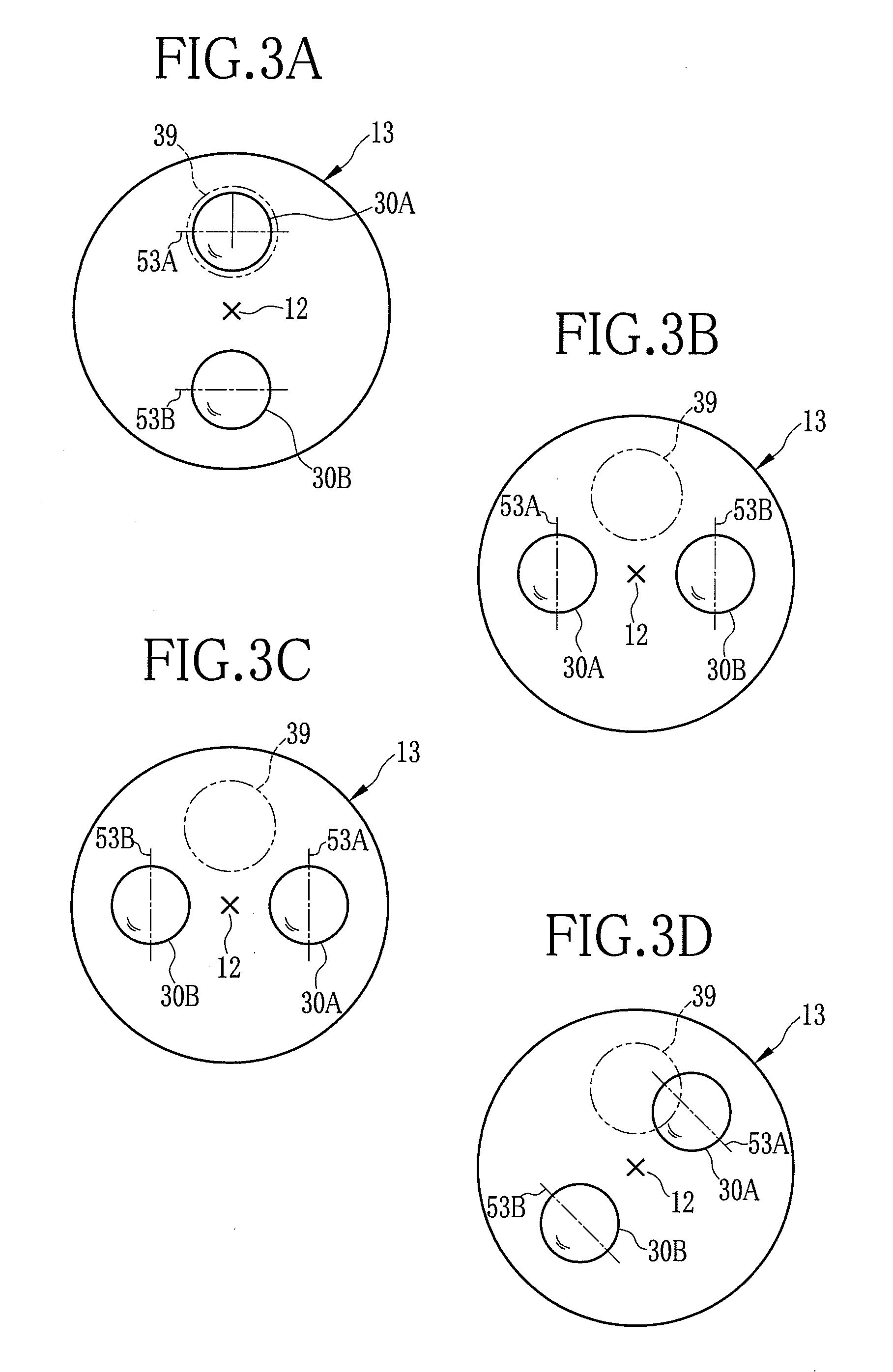
[0009]It is preferable that the lens barrel contains two of the imaging optical systems being arranged across the rotational center of the lens barrel and rotates among an ordinary position where the imaging optical systems are aligned vertical to each other, a first rotational position rotated approximately 90 degreed from the ordinary position in a first direction to align the imaging optical systems horizontal to each other, and a second rotational position rotated approximately 90 degreed from the ordinary position in a second direction which is direction opposite to the first direction to align the imaging optical systems horizontal to each other, and that the optical axis angle changing section enables panoramic image capturing by changing an angle between the optical axes of the imaging optical systems such that an overlap area of images captured with the imaging optical systems becomes small when the lens barrel is at the first rotational position, and enables stereoscopic image capturing by changing an angle between the optical axes of the imaging optical systems such that an overlap area of images captured with the imaging optical systems becomes large when the lens barrel is at the second rotational position.
[0010]It is preferable that the multi-eye image pickup device further comprises a power controlling section to power on the multi-eye image pickup device when the lens barrel is at the ordinary position, the first position or the second position, and to power off the multi-eye image pickup device when the lens barrel is at a third position different from the ordinary position, the first position and the second position. In this case, operation ability of the multi-eye image pickup is increased because a power button can be eliminated.
[0013]According to the multi-eye image pickup device of the present invention, the angle between the optical axes of the imaging optical systems is changed according to the rotational position of the lens barrel. Accordingly, various image capturing including the panoramic image capturing and the stereoscopic image capturing can be performed with the easy operation for changing the kind of image capturing.
[0014]Since the normal image capturing is set when the lens barrel is at the ordinary position, the panoramic image capturing is set when the lens barrel is rotated approximately 90 degree in the first direction from the ordinary position, and the stereoscopic image capturing is set when the lens barrel is rotated approximately 90 degree in the second direction from the ordinary position, the relations between the rotational positions of the lens barrel and the kinds of the image capturing become easy-to-understand and operation ability of the multi-eye image pickup is increased. In addition, when the converter lens barrel detachably attached to the camera body is provided, further various kinds of image capturing can be performed.

Problems solved by technology

Accordingly, there is a problem of operation ability.
In addition, Japanese Patent Laid-Open Publication No. 2003-298919 does not disclose the panoramic image capturing and the stereoscopic image capturing.

Method used


Image

  • Multi-eye image pickup device
  • Multi-eye image pickup device
  • Multi-eye image pickup device

Examples


Embodiment Construction

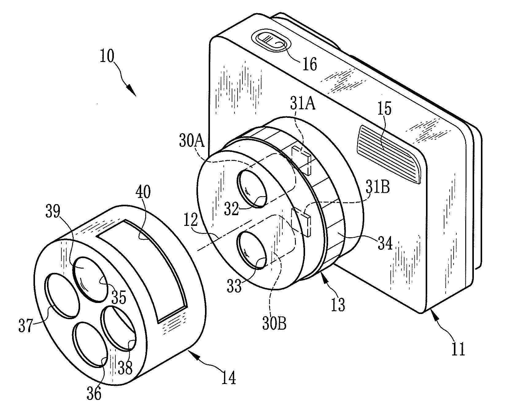
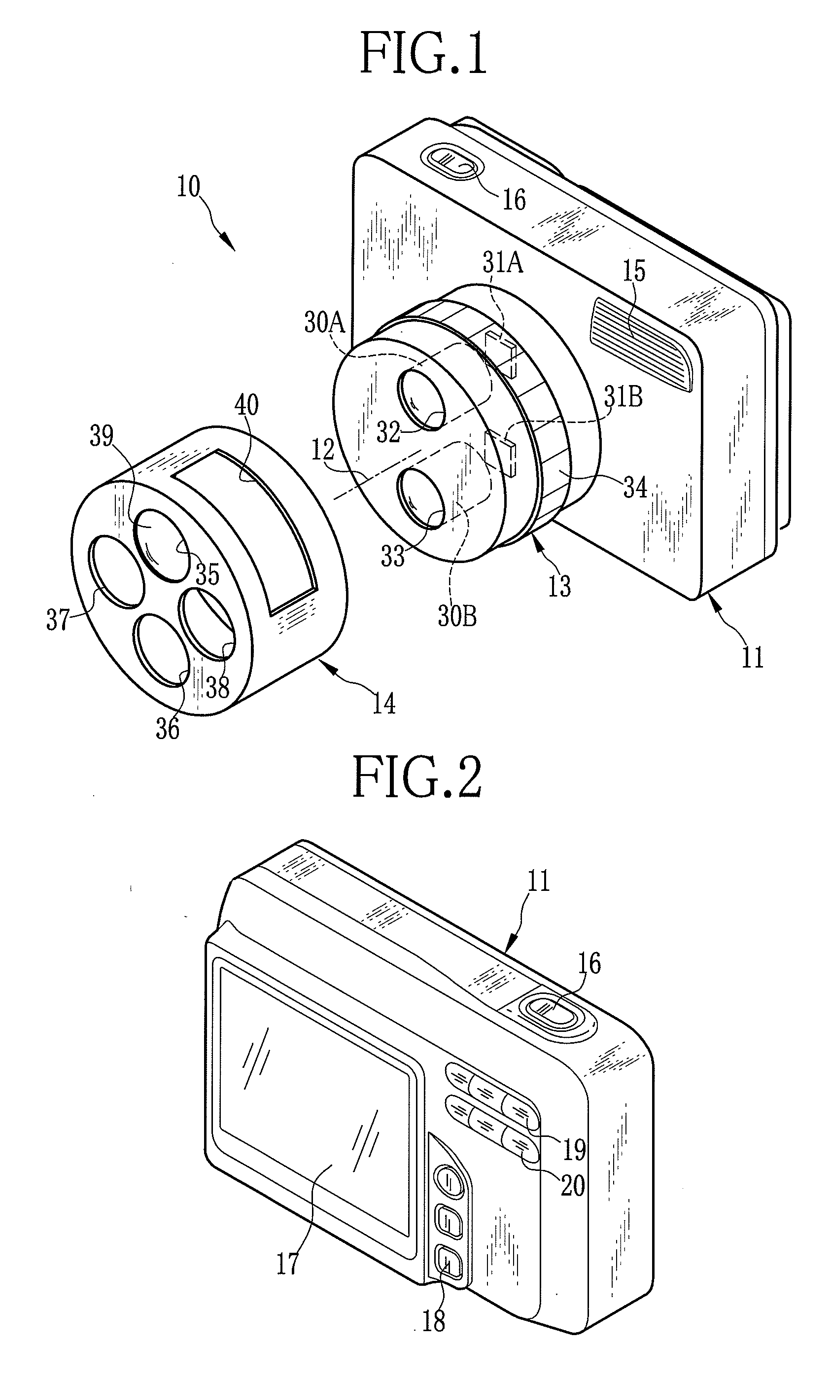
[0030]As shown in FIG. 1 and FIG. 2, a stereo camera (multi-eye image pickup device) 10 is composed of a camera body 11, a lens barrel 13 equipped rotatably around a rotation axis 12 at the front face of the camera body 11, and a converter lens barrel 14 detachably attached to the camera body 11 so as to cover the lens barrel 13. A flashlight emitter 15 is provided at the front face of the camera body 11, and a release button 16 is provided at the top face of the camera body 11 for being operated in image capturing. A liquid crystal panel 17 for displaying captured images and reproduction images, a panel operating section 18 which is operated with observing a display screen of the liquid crystal panel 17, and first and second zoom operating sections 19 and 20 are provided at the back face of the camera body 11.

[0031]The lens barrel 13 contains a first imaging optical system 30A, a second imaging optical system 30B, a first CCD image sensor (hereinafter referred to as the first CCD) ...


PUM


Abstract

A stereo camera comprises a camera body, a lens barrel rotatably attached to the camera body, and a converter lens barrel 14 detachably attached to the camera body. The lens barrel contains a pair of a first imaging optical system and a first CCD, and a pair of a second imaging optical system and a second CCD. When the lens barrel is at an ordinary position, a wide image capturing mode with only the first CCD being activated or a normal image capturing mode with only the second CCD being activated is set. When the lens barrel is at a first rotational position, a panoramic image capturing mode is set. When the lens barrel is at a second rotational position, a stereoscopic image capturing mode is set.

Description

BACKGROUND OF THE INVENTION[0001]1. Field of the Invention[0002]The present invention relates to a multi-eye image pickup device which enables to panoramic image capturing and stereoscopic image capturing.[0003]2. Description of the Related Arts[0004]Recently, digital cameras for converting subject light captured by a solid state imaging element such as a CCD image sensor into digital image data and recording the image data in a storage medium such as a built-in memory and a memory card are in widespread use. As one of such digital cameras, a multi-eye image pickup device (so-called stereo camera) having plural imaging optical systems and solid state imaging elements is known.[0005]Japanese Patent Laid-Open Publication No. 2004-120527 discloses a digital camera which has two pairs of an imaging optical system and a solid state imaging element and performs normal image capturing, panoramic image capturing and stereoscopic image capturing by changing an angle between the imaging optic...

Claims


Application Information

Patent Timeline
Patent Type & Authority Applications(United States)
IPC IPC(8): H04N5/225
CPCH04N13/0217H04N13/0239H04N13/0289H04N13/218H04N13/239H04N13/289
Inventor TAMURA, YOSHIO
Owner FUJIFILM CORP
Learn More