Floor pads

a technology for floor pads and pads, applied in the field of floor pads, can solve the problems of limiting the number of floor pads to be matched in one direction, and the inability to have different patterns of combination

Inactive Publication Date: 2007-03-15
LIN CHIEN JEN
View PDF4 Cites 9 Cited by
  • Summary
  • Abstract
  • Description
  • Claims
  • Application Information

AI Technical Summary

Benefits of technology

[0005] The present invention will become more obvious from the following description when taken in connection with the accompa

Problems solved by technology

The conventional floor pads have to include same shape of corners and angles or they cannot be matched with each other.
This limits the floor pads to be matched in one direction and cannot have different patterns of combination.

Method used


Image

  • Floor pads
  • Floor pads
  • Floor pads

Examples


Embodiment Construction

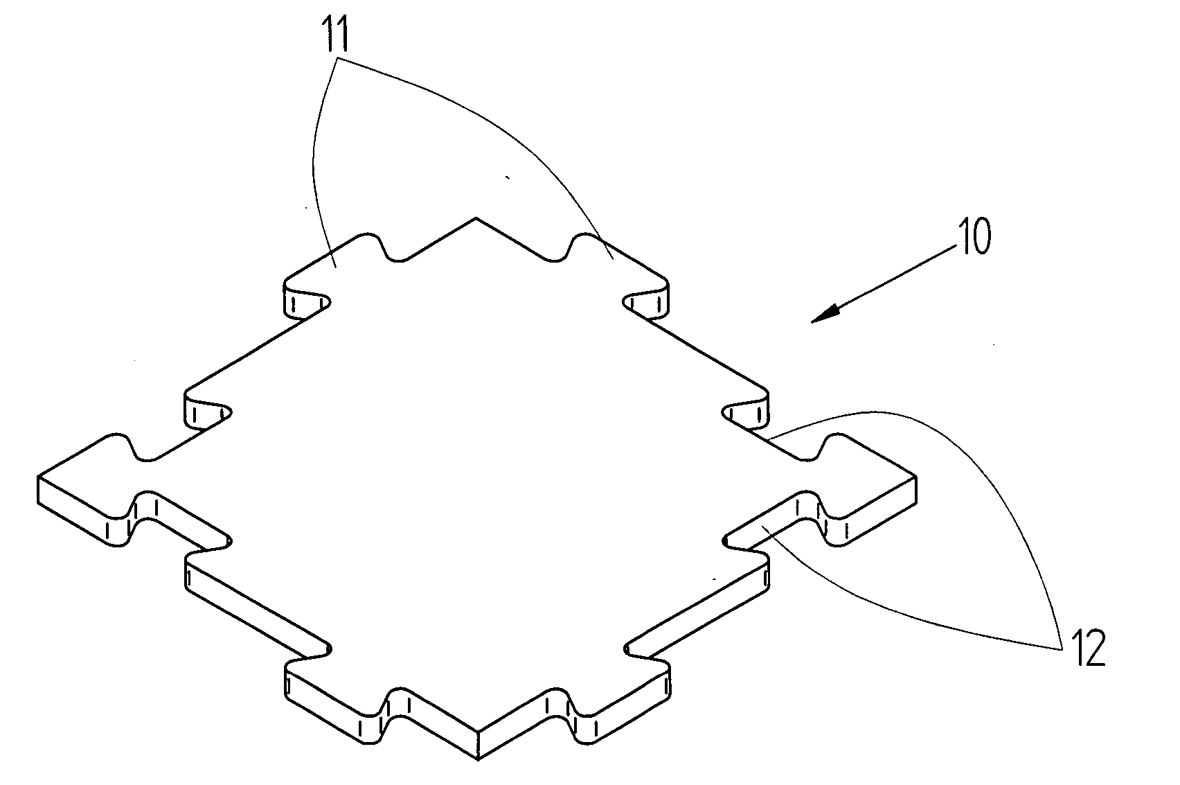
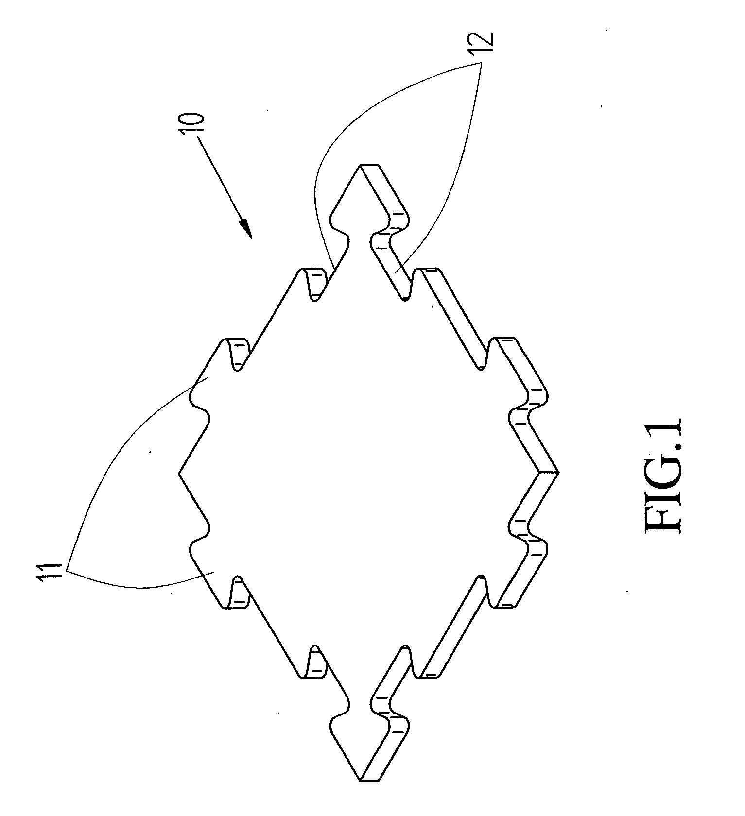
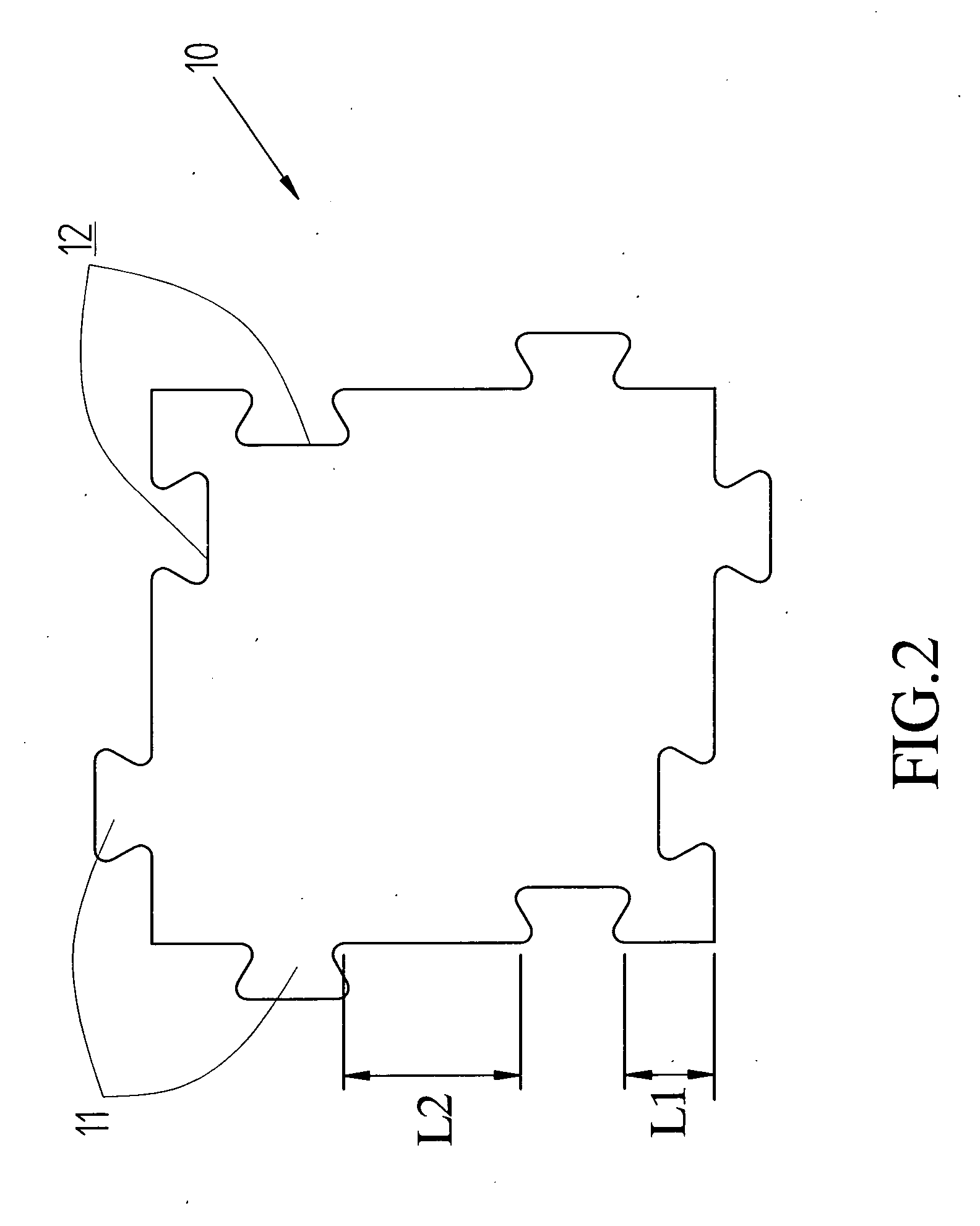
[0011] Referring to FIGS. 1 and 2, the floor pad 10 of the present invention is a square floor pad and comprises four sides and four right-angled corners. Two protrusions 11 extend from two adjacent sides of each of the two corners on a first diagonal axis of the pad 10 and two recesses 12 are defined in two adjacent sides of each of two corners on a second diagonal axis of the pad 10. The first and second diagonal axes are perpendicular with each other. The protrusions 11 are shaped to be matched with the recesses 12. A distal end of each of the protrusions 11 and an inside of each of the recesses 12 are located at two parallel horizontal planes. As indicated in FIG. 2, the length “L1” between one of the corners of the second diagonal axis of the floor pad 10 to the closest inner end of the recess is only half of the length “L2” from the other inner end of the recess 12 to the protrusion 11 on the same side of the floor pad 10.

[0012]FIG. 3 shows a first pattern of the combination ...


PUM


Abstract

A square-shaped floor pad includes two protrusions extending from two adjacent sides of each of the two corners on a first diagonal axis of the pad and two recesses are defined in two adjacent sides of each of two corners on a second diagonal axis of the pad. The protrusions are shaped to be matched with the recesses. The floor pads are able to be matched with each other by engaging the protrusion with the recesses in different directions and sides.

Description

FIELD OF THE INVENTION [0001] The present invention relates to floor pads which can be connected with each other in different ways. BACKGROUND OF THE INVENTION [0002] Conventional floor pads which are able to be connected with each other by engaging protrusions of one floor pad with recesses of another floor pad. The conventional floor pads have to include same shape of corners and angles or they cannot be matched with each other. The shapes of the protrusions and the recesses are designed to be matched with each other. This limits the floor pads to be matched in one direction and cannot have different patterns of combination. [0003] The present invention intends to provide a floor pad which includes two protrusions extending from two adjacent sides of each of two corners on a diagonal axis of the pad and two recesses are defined in two adjacent sides of each of two corners on another diagonal axis of the pad. The floor pads are allowed to be matched with each other in different dir...

Claims


Application Information

Patent Timeline
IPC IPC(8): B32B3/02B32B3/10
CPCE04F15/02Y10T428/16E04F2201/095E04F2201/091
Inventor LIN, CHIEN JEN
Owner LIN CHIEN JEN
Why Eureka
Try Eureka