
Method and system of purging water in air dryer of air pressure circuit

Inactive Publication Date: 2006-11-16
SMC CORP
View PDF0 Cites 1 Cited by
  • Summary
  • Abstract
  • Description
  • Claims
  • Application Information

AI Technical Summary

Benefits of technology

[0007] In view of the problem described above, a technical object of the present invention is to provide a method and a system of purging water in an air dryer of an air pressure circuit that can effectively dehumidify the compressed air supplied from a compressed air source by utilizing a small amount of secondary compressed air dehumidified in the air dryer.
[0010] In the system of purging water in the air dryer, the air dryer in the air pressure circuit may be composed of a membrane type air dryer for dehumidifying air by a membrane module. Further, it is effective to dispose a discharge path to a piping from an exhaust port of the switching valve to a purge flow path of the air dryer to discharge a part of exhaust air to the outside so that an increase in the back pressure of the cylinder can be suppressed. Further, it is possible to cause the air dryer to act as a silencer in an exhaust portion from the air pressure actuator.
[0011] In the method and the system of the present invention, a part of the secondary compressed air of the air dryer (5 to 10% of the flow amount of inlet air) is caused to flow as the purge air at all times, and, at the same time, the air exhausted from the actuator is entirely or partly caused to flow together with the compressed air and used as the purge air. Accordingly, almost all the dehumidified air can be effectively utilized without being wasted as compared with a conventional ordinary air dryer which uses only the secondary compressed air of an air dryer (10 to 40% of the flow amount of inlet air) as purge air.
[0013] As described above in detail, according to the present invention, a small amount of the secondary compressed air dehumidified in the air dryer is caused to flow together with the air exhausted from air pressure actuator, and the air flowing together is used as purge air to discharge the water separated from the compressed air in the dryer. As a result, the compressed air supplied from the compressed air source can be effectively dehumidified only by utilizing a small amount of the secondary compressed air dehumidified in the air dryer as the purge air, thereby a dew point can be reduced.

Problems solved by technology

By the way, a problem of dew condensation in actuators is arisen by recent reduction in size of the actuators.
However, since the membrane type air dryer generally requires a larger flow amount of purge air as a dew point is more reduced, there is contemplated a case in which a stable flow amount of purge air cannot be secured only by the air exhausted from the actuator.

Method used


Image

  • Method and system of purging water in air dryer of air pressure circuit
  • Method and system of purging water in air dryer of air pressure circuit

Examples


Embodiment Construction

[0015] The present invention will be explained in more detail based on an embodiment shown in the figure.

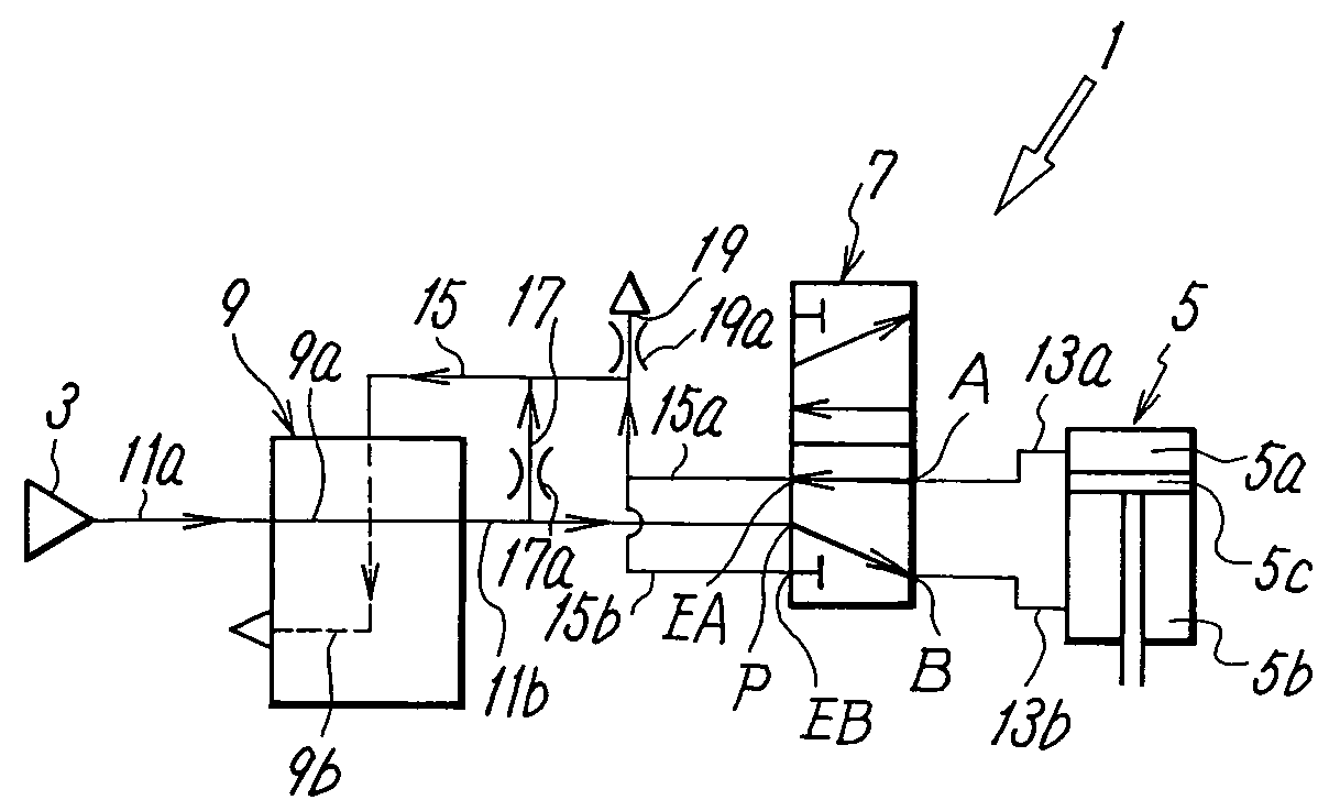
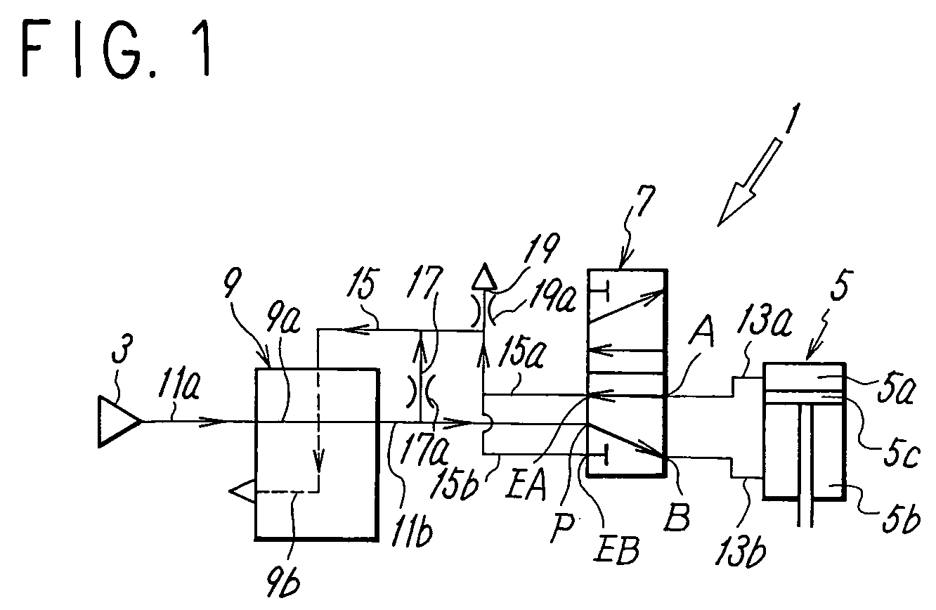
[0016]FIG. 1 conceptually shows an embodiment of a system for purging water in an air dryer of an air pressure circuit according to the present invention. The air pressure circuit 1 includes a compressed air source 3 composed of an air compressor and the like, an air pressure cylinder 5 as an example of an actuator driven by the compressed air supplied from the compressed air source 3, and a switching valve 7 for supplying and exhausting the compressed air, which is supplied from the compressed air source 3, to and from pressure chambers 5a, 5b on both the sides of a piston 5c of the air pressure cylinder 5. Then, a membrane type air dryer 9 is interposed between the compressed air source 3 and an inlet port P of the switching valve 7. The membrane type air dryer 9 dehumidifies the compressed air supplied from the compressed air source through a membrane module 9a.

[0017] The sw...


PUM


Abstract

To provide a method and a system of purging water in an air dryer that can effectively dehumidify compressed air only by utilizing a small amount of secondary compressed air dehumidified by the air dryer as purge air. In an air pressure circuit having an compressed air source, an air pressure cylinder driven by the compressed air supplied from the compressed air source, a switching valve for supplying and exhausting the compressed air to a pressure chamber of the air pressure cylinder, and an air dryer interposed between the compressed air source and an inlet port of the switching valve, the compressed air from the compressed air source is dehumidified in the air dryer, a part of the dehumidified secondary compressed air is caused to flow together with the air discharged from the air pressure cylinder, and the air flowing together is supplied to a purge flow path of the air dryer as purge air.

Description

TECHNICAL FIELD [0001] The present invention relates to a water purge method for discharging the water separated from compressed air in an air dryer of an air pressure circuit for driving an air pressure actuator by compressed air supplied from a compressed air source and to a water purge system of the air dryer of the air pressure circuit making use of it. BACKGROUND ART [0002] An air pressure circuit as disclosed in, for example, Patent Document 1 is known as an air pressure circuit for driving an air pressure actuator by the compressed air supplied from a compressed air source. [0003] Air pressure circuits of this type dispose a membrane type air dryer between an air source and an inlet port of a switching valve to dehumidify air by a membrane module and connect an exhaust port of the switching valve a purge flow path of the membrane type air dryer. With this arrangement, since dehumidified air can be entirely used to drive the air pressure actuator, the dehumidified air is not w...

Claims


Application Information

Patent Timeline
IPC IPC(8): B01D53/02
CPCB01D53/268B01D53/26
Inventor SADACHIKA, TETSUO
Owner SMC CORP
Learn More