Waveform display device capable of connecting to network

a technology of display device and waveform monitor, which is applied in the direction of digital variable/waveform display, measurement device, instruments, etc., can solve the problem that the computer cannot timely remote monitor the image displayed on the display of the waveform monitor

Inactive Publication Date: 2006-10-05
LEADER ELECTRONICS
View PDF4 Cites 2 Cited by
  • Summary
  • Abstract
  • Description
  • Claims
  • Application Information

AI Technical Summary

Benefits of technology

[0016] An object of the present invention is to provide a waveform monitor for timely remote-monitoring the image displayed on the display.
[0017] Another object of the present invention is to provide the waveform monitor for timely remote-monitoring the transmission status and / or the waveform status of the compressed transmission signal.

Problems solved by technology

As a result, the computer could not timely remote-monitor the image displayed on the display of the waveform monitor.

Method used


Image

  • Waveform display device capable of connecting to network
  • Waveform display device capable of connecting to network
  • Waveform display device capable of connecting to network

Examples


Embodiment Construction

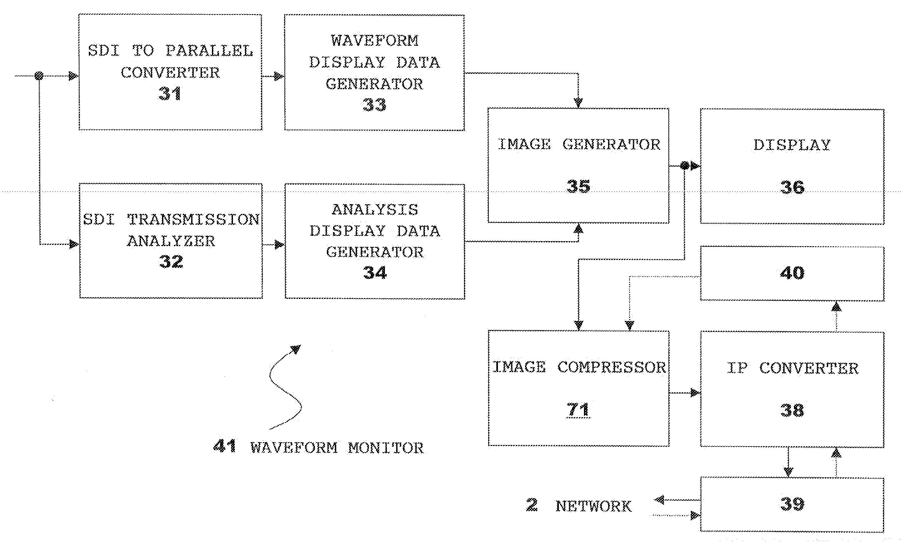
[0034]FIG. 7 is a schematic functional block diagram of a waveform monitor 41 of the present invention. As shown in FIG. 7, the waveform monitor 41 includes a converter 31, a generator 33, an analyzer 32, a generator 34, an image generator 35, a display 36, an IP converter 38, an interface 39 and a controller 40, as in the conventional waveform device. Further, the waveform monitor 41 includes an image compressor 71 instead of an image capturer 37.

[0035] The converter 31 converts an SDI signal into parallel data; and the generator 33 converts the parallel data into waveform display data. The generator 33 preferably also converts the parallel data into vectorscope display data and / or video display data. Note that the generator 33 may generate other display data from the parallel data. The generator 33 outputs the display data (for example, a waveform display, a vectorscope display data and a video display data) to the image generator 35. When the generator 33 outputs a plurality of ...


PUM


Abstract

A waveform monitor comprises: means (35) for generating image data including at least waveform display data of a video signal; means (36) for displaying the image data; means (71) for generating moving image data compressed in a predetermined format from the image data; a converter (38) for packetizing the moving image data; and interface means (39) for outputting the packetized moving image data to a network. The waveform monitor can further comprise means (51) for converting a compressed video signal to uncompressed parallel data, the waveform display data is converted from the parallel data.

Description

BACKGROUND OF THE INVENTION [0001] The present invention relates to a waveform monitor capable of connecting to a network, more specifically, to the waveform monitor capable of compressing image data displayed on a display and outputting to the network. [0002] (Remote monitoring) [0003]FIG. 1 is a view for schematically explaining a video signal monitoring system. As shown in FIG. 1, the video signal monitoring system includes a computer 1, a network 2, and N waveform monitors 3-1, ..., 3-N. The computer 1 can remotely operate each of the waveform monitors 3 through the network 2, and a software allowing such a remote operation is disclosed in, for example, Leader Electronics Corp., “FS 3019 (Products)”, internet <URL: http: / / www.leader.co.jp / english / product / fs_3019_e.html>to be mentioned later. [0004] For example, when the computer 1 instructs a certain waveform monitor 3-1 to capture an image displayed on a display of the waveform monitor 3, the waveform monitor 3 sends a ca...

Claims


Application Information

Patent Timeline
IPC IPC(8): G01R13/02
CPCG01R13/345G01R13/029
Inventor IMAMURA, GENICHI
Owner LEADER ELECTRONICS
Why Eureka
Try Eureka