Tube clamp device and tube connection device

a tube clamp and tube connection technology, applied in the direction of diaphragm valves, photosensitive materials, instruments, etc., can solve the problems of reducing operability or work efficiency remarkably, affecting the operation of the operator, so as to achieve enhanced operability for the operator

Active Publication Date: 2006-07-06
TERUMO KK
View PDF4 Cites 23 Cited by
  • Summary
  • Abstract
  • Description
  • Claims
  • Application Information

AI Technical Summary

Benefits of technology

[0018] According to the first aspect of the present invention, because the elastic member of the movable clamp deforms elastically to engage the protruded portion with the movable clamp section, since pressing force applied to the movable clamp can be smaller than that of the conventional tube clamp apparatus while maintaining engagement between the placement clamp section and the movable clamp section, an effect that operability for an operator can be enhanced, can be obtained.
[0019] According to the second aspect, in addition to the effect in the first aspect, because parts can be lowered in being worn away at a time of engagement operation, since the holding unit holds the tubes in an appropriate flat state even in high frequency of use, an effect that cutting and connecting of the tubes according to the cutting unit and the movement unit are carried out properly, can be obtained.

Problems solved by technology

The conventional tube connecting apparatuses can maintain holding power by employing the above stated structures, but they request an operator large pressing force (load) at a time of locking the covering body so as the covering body not to open with a hook member, which lowered operability or work efficiency remarkably.
Further, because the hook member and the engagement member are made of metal having high rigidity, abrasion is caused (parts are worn away) at a time of engagement operation therebetween.
This weakens locking power (power for maintaining pressing state against the tube(s)) between the both, depending that the mechanism is going on use, consequently, there was a case that the mechanism had a difficulty in maintaining pressing force against the tube(s) in a proper flat state.

Method used


Image

  • Tube clamp device and tube connection device
  • Tube clamp device and tube connection device
  • Tube clamp device and tube connection device

Examples


Embodiment Construction

[0037] With reference to the drawings, an embodiment of a tube connecting apparatus that cuts and then connects two tubes in which blood is contained and sealed and to which the present invention is applied will be explained.

[0038] (Structure)

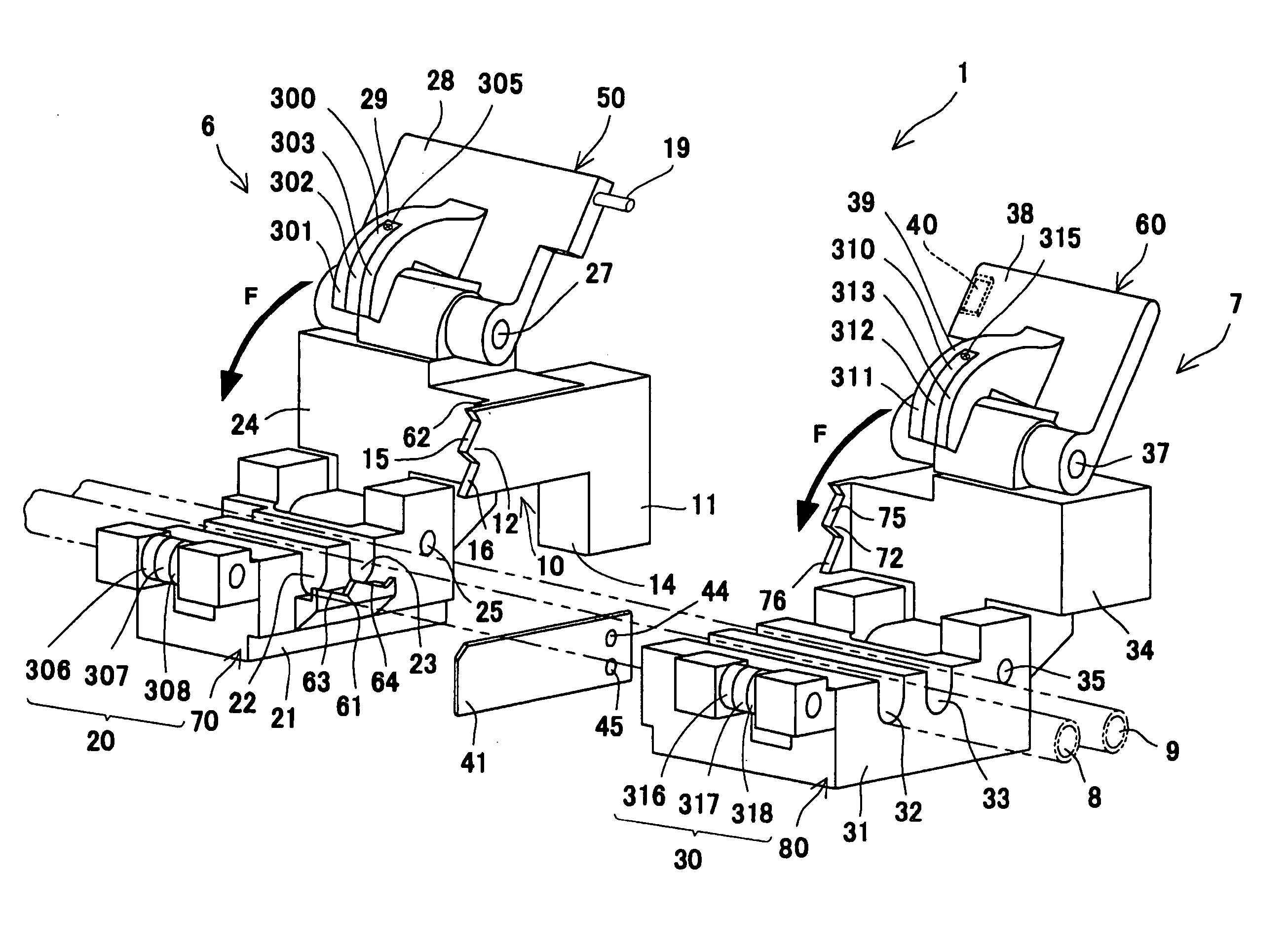
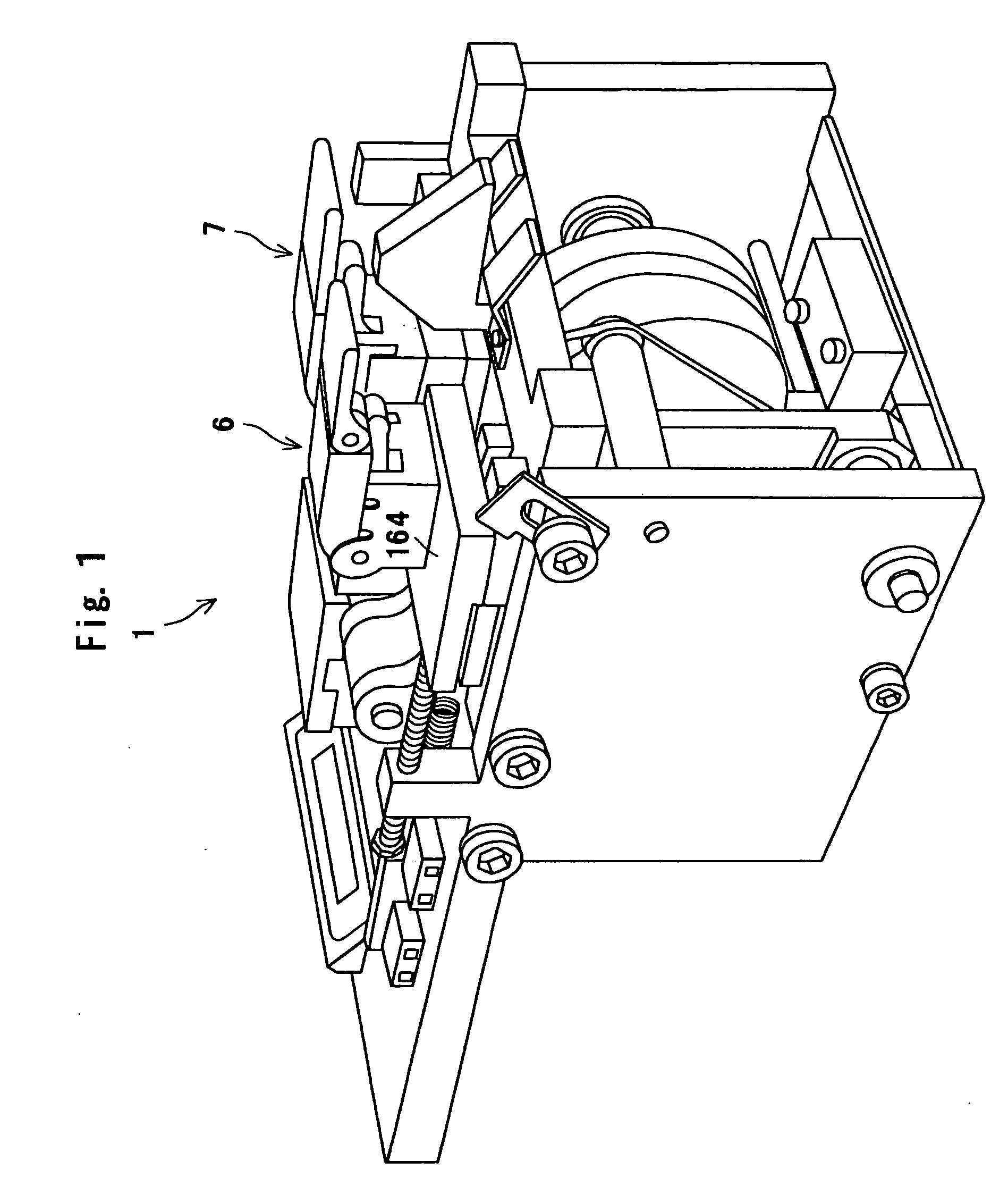
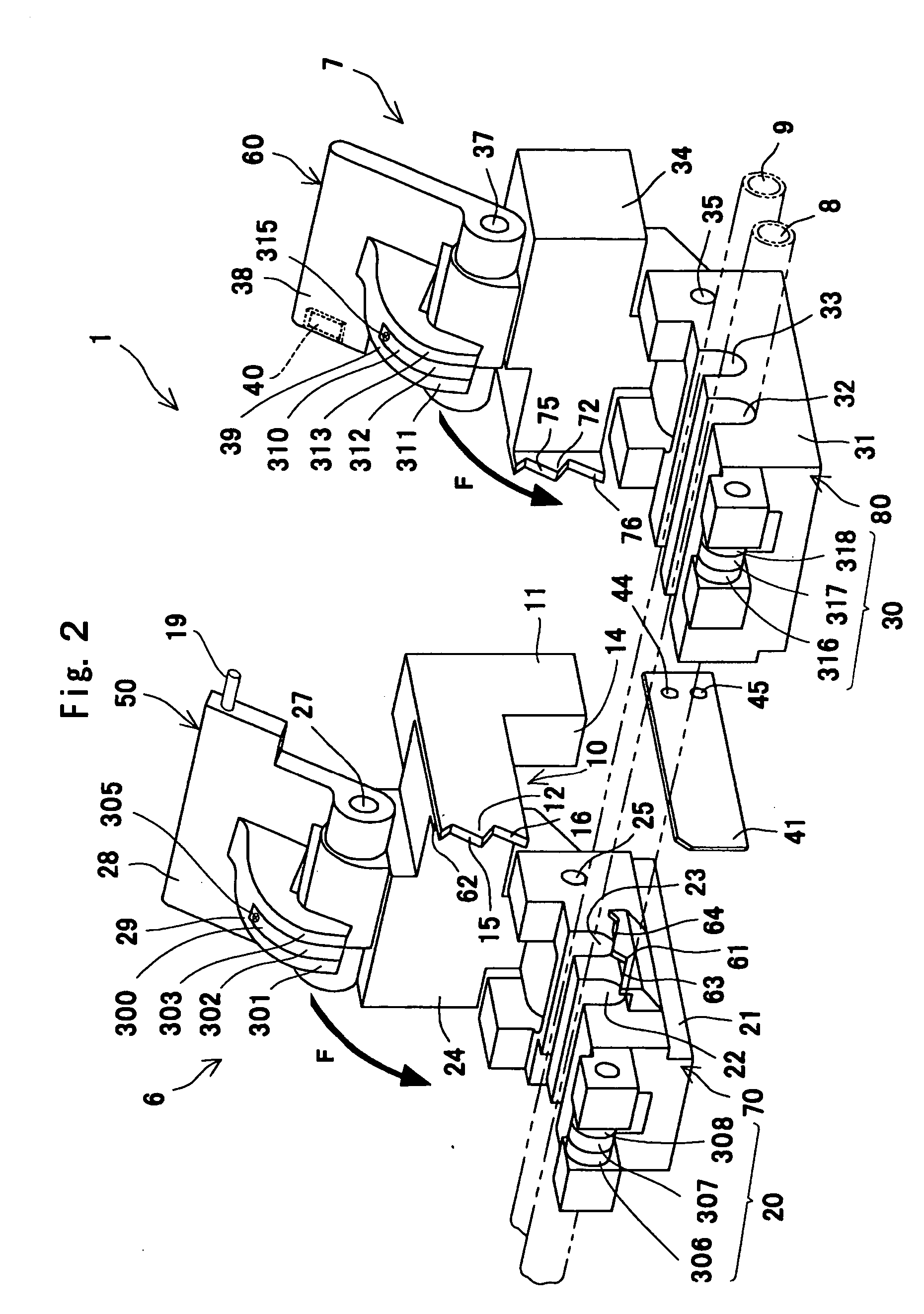
[0039] As shown in FIG. 1 and FIG. 2, a tube connecting apparatus 1 of the present embodiment is equipped with a first clamp 6 serving as a tube clamp apparatus (a first holding section) and a second clamp 7 serving as a tube clamp apparatus (a second holding section), both of which hold two flexible tubes 8, 9 approximately in a parallel state, and a tube-pushing member 10 which is disposed between the first clamp 6 and second clamp 7 and adjacent to the first clamp 6 to press the tubes 8, 9 to a flat state. The tube connecting apparatus 1 is accommodated in an unillustrated casing such that protruded members as shown in FIG. 1 are hidden. (See FIG. 3.)

[0040] The first clamp 6 has a first lower jaw portion 70, which forms a lower jaw of the...


PUM

PropertyMeasurementUnit
flexibleaaaaaaaaaa
elastic deformationaaaaaaaaaa
elasticaaaaaaaaaa

Abstract

A tube clamp apparatus and a tube connecting apparatus having high durability and improved operability when an operator locks these apparatuses are provided. A tube connecting apparatus comprises a first clamp and a second clamp, each pressing to hold two flexible tubes 8, 9. The tubes are placed at a lower jaw portion of the second clamp and pressed to a flat state by pressing force applied thereto a direction of an arrow A. A hook section 310 having hook portions divided into plural pieces is set up at an upper jaw portion of the second clamp, and the hook portion B 312 is made of a POM elastic member having, on one side thereof, a protruded portion 314 protruded from other adjacent hook portions. When pressing force is applied to the upper jaw portion, the hook portion B 312 protruded from the other adjacent hook portions is elastically deformed and engaged with a POM-made roller B 317 to prevent back-tracking of the hook section 310.

Description

FIELD OF THE INVENTION [0001] The present invention relates to a tube clamp apparatus and a tube connecting apparatus, and in particular relates to a tube clamp apparatus which presses to hold a flexible tube in a flat state and a tube connecting apparatus which connects flexible tubes each other. DESCRIPTON OF RELATED ART [0002] Conventionally, in a case that tube connecting between a blood-collecting bag and a blood-component bag in a blood transfusion system, exchanging between a dialytic-fluid bag and a waste-fluid bag in continuous ambulatory peritoneal dialysis (CAPD) or the like is carried out, it is necessary to connect tubes under a sterilized condition. For example, in JPB 61-30582, a tube connecting apparatus equipped with a pair of holders capable of holding two tubes to be connected in parallel and a cutting plate (plate-shaped heater element, wafer) capable of moving across the tubes which are placed between both of the holders is disclosed. In this tube connecting app...

Claims


Application Information

Patent Timeline
Patent Type & Authority Applications(United States)
IPC IPC(8): F16K7/04A61M39/02A61M1/14A61M39/14B29C65/20B29L23/00
CPCA61M1/14B29C66/961B29C65/2046B29C65/7802B29C65/7841B29L2023/007B29C65/2061B29C66/1142B29C66/5221B29C66/857B29C66/818B29C66/91651B29C66/91231B29C66/91421B29C66/91431B29C66/91213A61M39/146B29C65/2076B29C66/71B29C66/7373B29C66/8167B29C65/203B29C66/0018B29C66/73921B29C65/30B29K2027/06B29C65/74B29C65/20A61M39/02
Inventor ISHIDA, SHINJIYAMANUSHI, SATOSHI
Owner TERUMO KK
Why Eureka
Try Eureka