
Image display apparatus

a technology of image display and display screen, which is applied in the field of image display apparatus, can solve the problems of inability to improve compactness, difficult for flexible display material to become as flexible as thin film, and linear missing parts of displayed image at the border of adjacent display screen, etc., and achieves the effect of enlarged display screen, convenient viewing, and high portability

Inactive Publication Date: 2006-03-09
FUJIFILM CORP
View PDF12 Cites 154 Cited by
  • Summary
  • Abstract
  • Description
  • Claims
  • Application Information

AI Technical Summary

Benefits of technology

[0010] As the image display apparatus has the two frames which are openable and closable, it can become more compact by closing the two frames and can realize a seamless display screen across the two frames when they are opened.
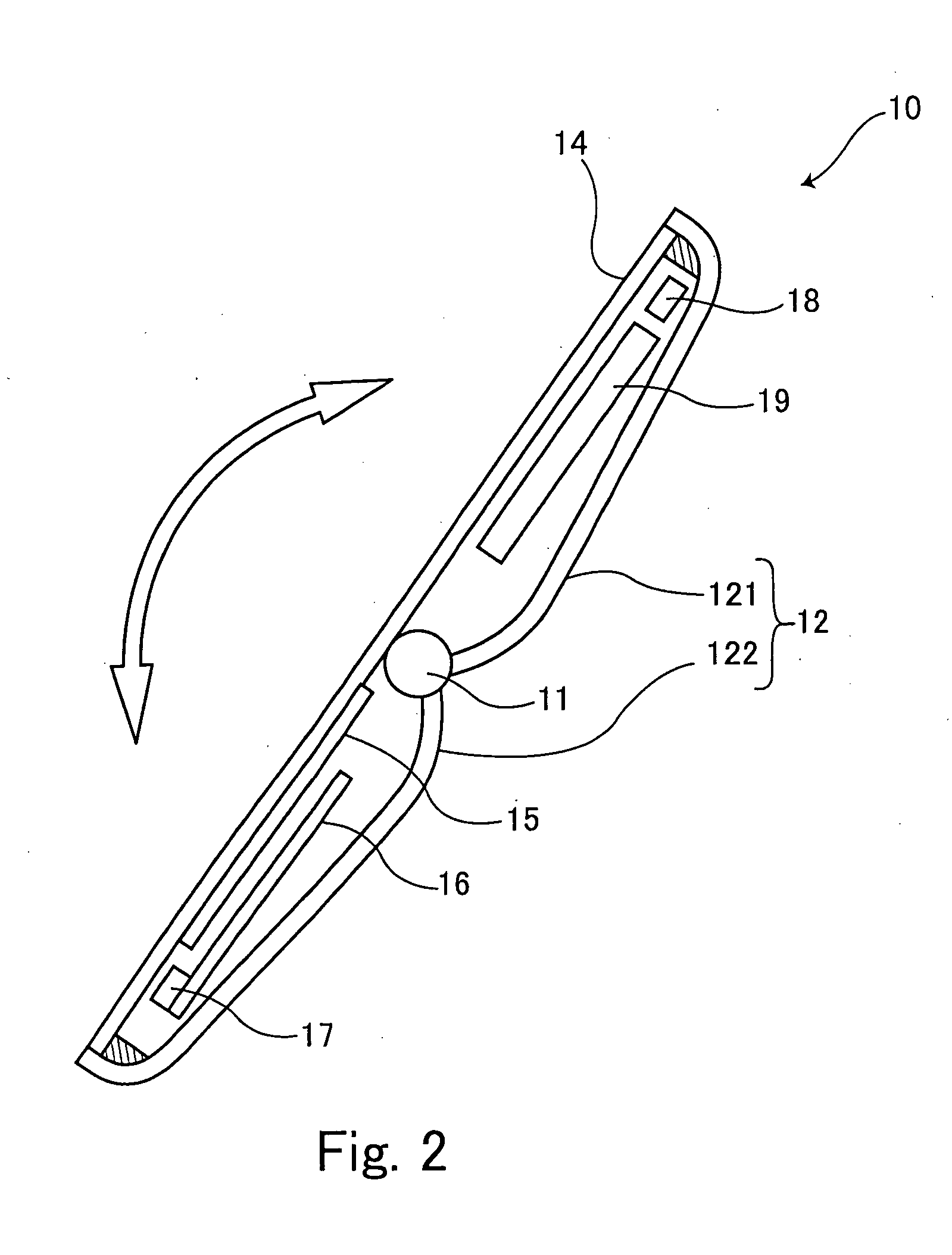
[0012] The display screen is flexible but is folded into two with its part being curved without putting any crease on the display screen. Therefore space is created in the center inside the folded display screen. By arranging the unit in the space, the space is utilized enhancing compactness and portability.
[0015] Accordingly, the present invention can provide the image display apparatus with a high level of portability and enlarged display screen.
[0016] Moreover, the image display apparatus of the present invention does not put any crease or broken line on the display screen, making it easy to see. When it is carried, the display screen is vulnerable due to its structure. But with protection with the rigid frames can prevent the display screen from scratches and damage.

Problems solved by technology

However, although Japanese Patent No. 2645306 can enhance compactness by folding the plural display screens, it has a defect in that when an image is displayed on the whole of plural display screens there are linear missing parts on the displayed image at the border of adjacent display screens.
In addition, Japanese Patent Publication Nos. 2001-100661, 2003-309744 still require space to spread flexible display material which has been rolled up.
Therefore, compactness cannot be improved solely by the mechanism of rolling up the flexible display material.
Furthermore, although Japanese Patent Publication No. 2003-309744 describes that the flexible display material can be rolled up to be an extremely small-diameter roll, it is difficult for the flexible display material to become as flexible as a thin film.

Method used


Image

  • Image display apparatus
  • Image display apparatus
  • Image display apparatus

Examples


first embodiment

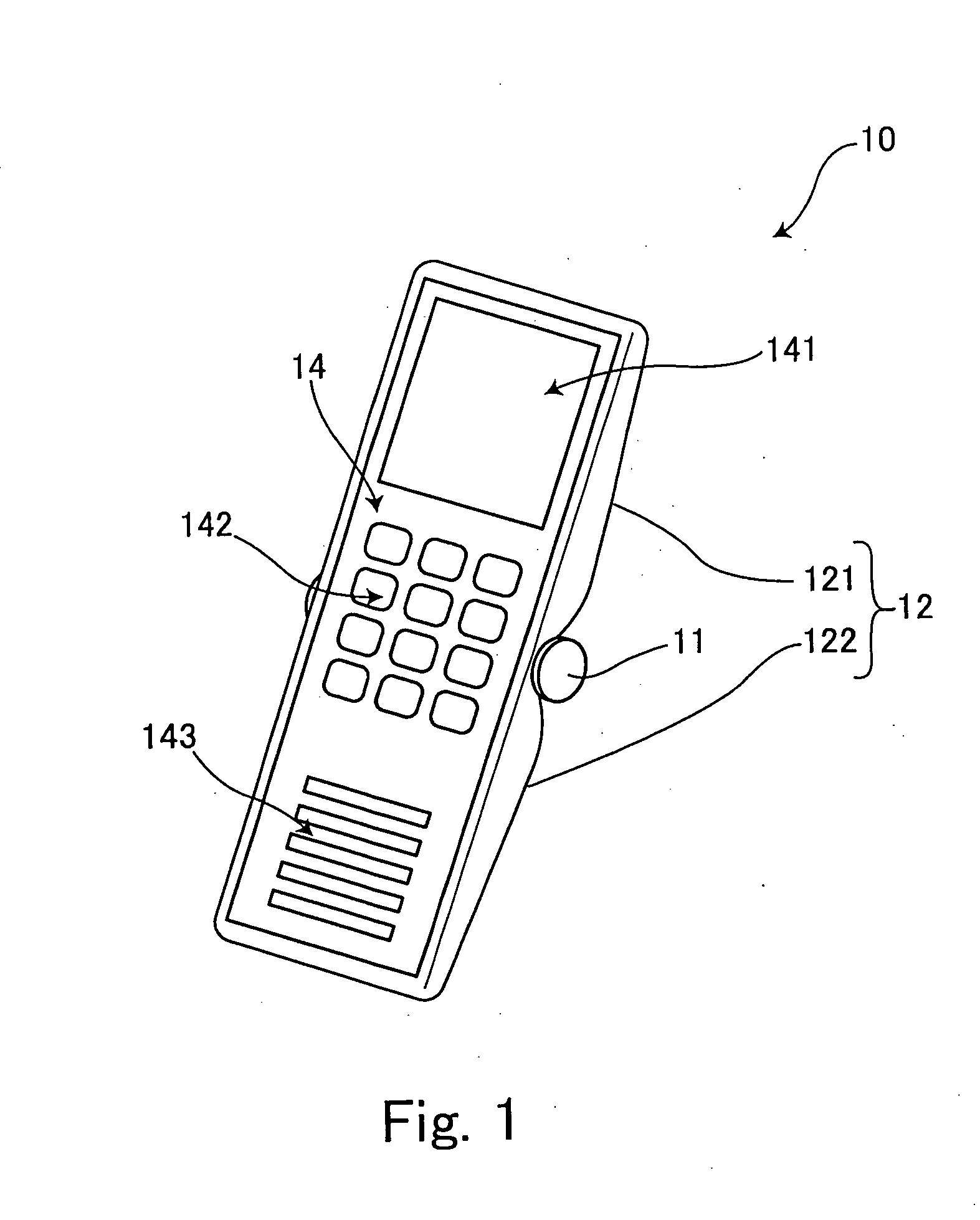
[0042]FIG. 1 is an external view of an image display apparatus according to the present invention, FIG. 2 is a sectional view of the image display apparatus shown in FIG. 1 when it is opened, and FIG. 3 is a sectional view of the image display apparatus shown in FIG. 1 when it is closed.

[0043] An image display apparatus 10 can be used as a mobile phone. As shown in FIG. 1, the image display apparatus 10 is provided with a cover 12 having two frames 121 and 122 linked through a pivot 11 each of which is closable and openable. The cover 12 is made of hard material such as hard plastics to protect the image display apparatus. A display screen 14 is arranged inside the two frames 121 and 122 when they are closed so as to become flat being supported at the ends thereof by the two frames when they are opened. As shown in FIG. 1, the display screen 14 composes a screen 141, push buttons 142 and a menu image 143 which are part of the displayed image, but their appearances are similar to the...

second embodiment

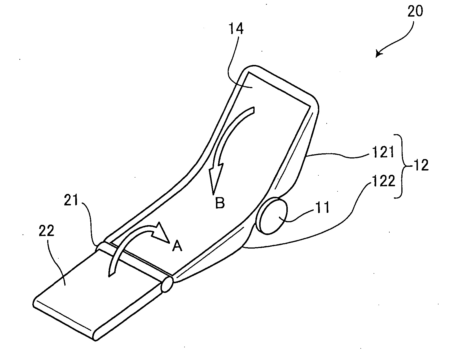
[0048]FIG. 4 is an external perspective view of an image display apparatus when it is opened and FIG. 5 is a sectional view of the image display apparatus shown in FIG. 4 when it is closed. In order to make it easy to understand, the same elements as those shown in FIGS. 1 to 3 are designated with the same reference characters as those in FIGS. 1 to 3 irrespective of minor difference in a form. The same is applied to the other embodiments.

[0049] As indicated in FIG. 4, an image display apparatus 20 according to a second embodiment has a battery unit 22. The battery unit 22 is pivotably supported by a pivot 21 relative to one frame 122 of the two frames that compose a cover 12. By employing the battery unit 22, it is possible to make the apparatus thinner and smaller by eliminating the battery 19 (see FIG. 2) incorporated in the apparatus according to the first embodiment. It is also possible to enhance battery capacity by adding the battery unit 22 to the battery unit 19.

[0050] Th...

third embodiment

[0053]FIG. 6 is an external perspective view of an image display apparatus when it is opened according to the present invention and FIG. 7 is a perspective view of the image display apparatus shown in FIG. 6 when it is closed.

[0054] The image display apparatus according to the third embodiment shown in FIGS. 6 and 7 also has a battery unit 32 linked through a pivot 31 to the frame 121. According to the second embodiment the battery unit 22 is linked to the frame 122 through the pivot 21 which is parallel to the pivot 11, a link between the two frames 121 and 122 as shown in FIG. 4. However, in the image display apparatus 30 according to the third embodiment shown in FIGS. 6 and 7, the battery unit 32 is linked to the side-edge of the frame 121 through the pivot 31 which is perpendicular to the pivot 11. Similarly to the second embodiment, the battery unit 32 according to the third embodiment can pivot between a housed position where it is placed on the display screen 14 by being piv...


PUM


Abstract

An image display apparatus have two frames, a flexible image display screen and a unit. The two frames mutually closable and openable are linked through a pivot. When the two frames are closed, the flexible image display screen is arranged inside the two frames, being folded into two with its part being curved. The image display screen is opened when the two frames are opened. The unit is supported by one of the two frames so as to pivot freely between a housed position and a position in the use of the display screen. The housed position is where the unit is placed on the display screen. When the display screen is in use, the unit is moved outside the display screen. By turning the unit to the housed position and closing the two frames, the unit is further housed in the position sandwiched by the folded display screen.

Description

BACKGROUND OF THE INVENTION [0001] 1. Field of the Invention [0002] The present invention relates to an image display apparatus which displays an image. [0003] 2. Description of the Related Art [0004] Recently, there is a demand for a mobile phone with enhanced compactness and a bigger display screen. In order to meet such a demand which seems contradictory, there has been proposed a technique that an image is displayed on the whole of plural display screens which are closably and openably linked, thus realizing the function equivalent to an enlarged display screen (see Japanese Patent No. 2645306). Another technique has been proposed with the use of recent flexible display material such as organic EL display material that the flexible display material is rolled up in order to be put away while it is spread at the time of use in order to enlarge a display screen (see Japanese Patent Publication Nos. 2001-100661, 2003-309744). [0005] However, although Japanese Patent No. 2645306 can ...

Claims


Application Information

Patent Timeline
Patent Type & Authority Applications(United States)
IPC IPC(8): H04N5/222
CPCG06F1/1616G06F1/1635G06F1/1652G06F1/1679G09F9/301G06F1/1698H04M1/0216H04M1/0247H04M1/0268G06F1/1686G06F1/1626
Inventor MISAWA, ATSUSHI
Owner FUJIFILM CORP
Learn More