
System and method for variable rate multiple access short message communications

a short message and variable rate technology, applied in the field of communication systems, can solve the problems of system efficiency when transmitting only short bursts of data at low duty cycles, and the message size is too short for some applications, so as to facilitate increased message size, and efficiently use the frequency spectrum

Active Publication Date: 2005-11-24
GENERAL DYNAMICS MISSION SYST INC
View PDF13 Cites 146 Cited by
  • Summary
  • Abstract
  • Description
  • Claims
  • Application Information

AI Technical Summary

Benefits of technology

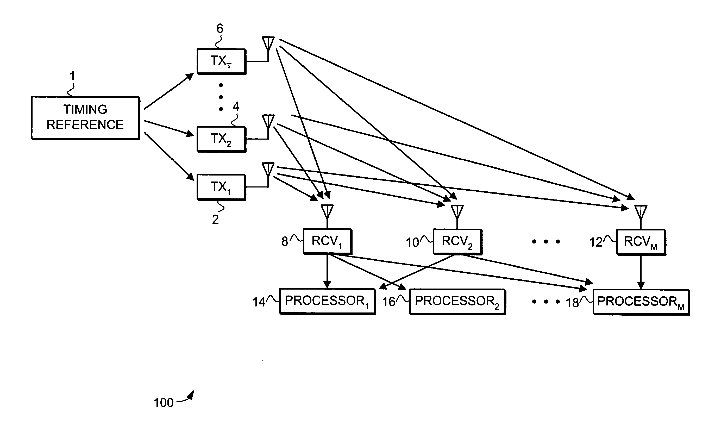
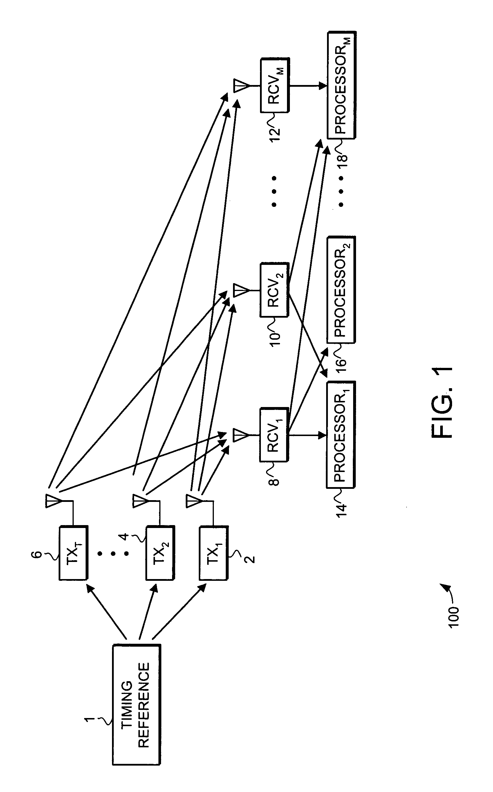
[0009] The present invention provides a communication system and receiver that facilitates increased message size in a communication system that supports a large number of transmitters sharing a common frequency band. The communication system facilitates increased message size by incorporating a plurality of transmit bit sets in each burst of data. The additional transmit bit sets are incorporated into a plurality of transmit codes that are generated using at least one additional spreading code that is orthogonal to the base spreading code. The plurality of transmit codes are then combined into one composite message and the composite message is spread again using another scrambling sequence. The final composite spread message is transmitted to the receiver in the appropriate message time slot.
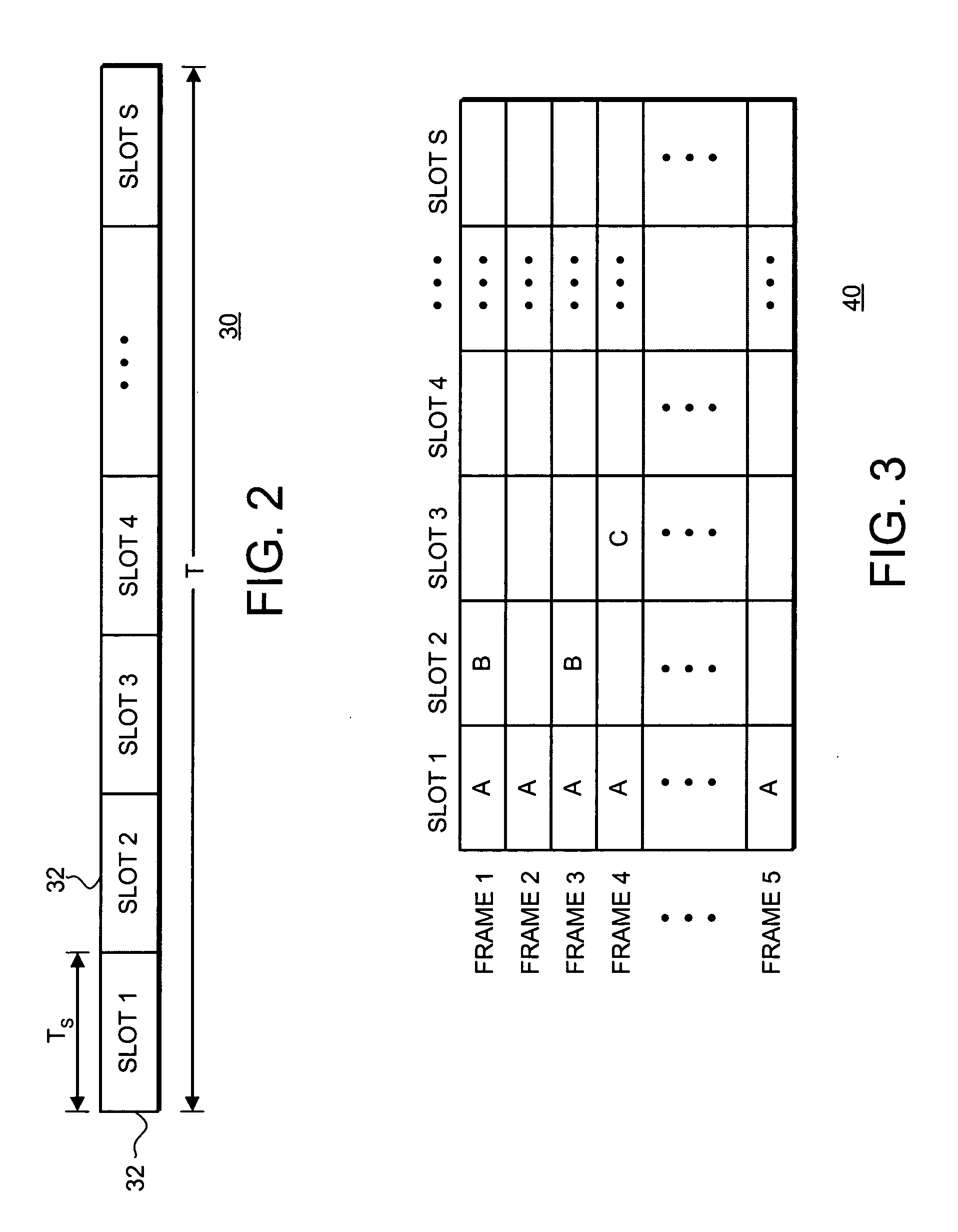
[0010] The communication system is thus implemented using code division multiplexing (CDM) and time division multiple access (TDMA) techniques for transmitting bursts of data while efficiently using the frequency spectrum and supporting a large number of transmitters / users. Specifically, many users of the communications system share a common frequency band, but each transmit their respective message bursts of data at different and specific times via a TDMA technique, as defined by the system. The communication system facilitates increased message size by using CDM techniques that use a plurality of additional spreading codes that are orthogonal to the base spreading code. The CDM techniques facilitate the transmission of multiple transmit bit sets in each TDMA burst of data. To facilitate synchronization of the CDM / TDMA technique, each transmitter of the system is synchronized to a common timing reference thereby abating the need to maintain synchronization between the transmitters and receivers of the system and the need for a full duplex radio link.

Problems solved by technology

However, while CDMA systems have a “soft-capacity” in that additional users may be added with only slight system degradation, such systems are not efficient when transmitting only short bursts of data at low duty cycles.
Unfortunately, these systems require synchronization between transmitters and receivers requiring a full duplex radio link and have been limited in the message size that can be sent to each user.
This message size is too short for some applications.

Method used


Image

  • System and method for variable rate multiple access short message communications
  • System and method for variable rate multiple access short message communications
  • System and method for variable rate multiple access short message communications

Examples


first embodiment

[0045] In first embodiment illustrated in FIG. 4A, each transmit bit set 1-M includes d bits of data as identified by blocks 59 transmitted concurrently with the d bits of data transmitted in the base transmit bit set 0. Additionally, in the embodiment illustrated in FIG. 4A the data bits transmitted in the base transmit bit set 0 and the transmit bit sets 1-M are all part of message 1. Thus, the embodiment of FIG. 4A is able to transmit one message with a total of [(d+1)*M] data bits. This is a significant increase over prior systems that would have been limited to the d bits of the base message. In some implementations, the transmission of bits on transmit bit sets 1-M can result in an 8 to 10× increase in message length, and with an increase in transmit power, can result in a 50 to 100× increase in message length.

second embodiment

[0046] In the second embodiment illustrated in FIG. 4B, each transmit bit set 1-M again includes d bits of data as identified by blocks 59 transmitted concurrently with the d bits of data transmitted in the base transmit bit set 0. In the embodiment illustrated in FIG. 4B the data bits transmitted in transmit bit set 0 are part of message 1, and the data bits transmitted in transmit bit sets 1-M are all part of message 2. Thus, the embodiment of FIG. 4B is able to transmit one message with d data bits and one message with (d*M) data bits. Again, this is a significant increase over prior systems that would have been limited to the d bits in the first message.

third embodiment

[0047] In the third embodiment illustrated in FIG. 4C, each transmit bit set 1-M includes (d+p+f) bits of message data as identified by blocks 61 transmitted concurrently with the p, f and d bits of data transmitted in the base transmit bit set 0. In the embodiment illustrated in FIG. 4C the data bits transmitted in transmit bit set 0 and the data bits transmitted in transmit bit sets 1-M are all part of message 1. Thus, the embodiment of FIG. 4C is able to transmit one message with [(M*(d+p+f))+d]data bits. Because d+p+f data bits can be transmitted in each of the transmit bit sets 1 through M, the embodiment illustrated in FIG. 4C can transmit an even larger message than those illustrated in FIGS. 4A and 4B. However, this embodiment additional buffering is typically required in the receiver as the receiver is synchronized to the P bits of the preamble and the transmit bits 1 though M arrive before this synchronization is achieved.


PUM


Abstract

A communication system and receiver is provided that facilitates increased message size in a communication system that supports a large number of transmitters sharing a common frequency band. The communication system facilitates increased message size by incorporating a plurality of transmit bit sets in each burst of data. The additional transmit bit sets are incorporated into a plurality of transmit codes that are generated using at least one additional spreading code that is orthogonal to the base spreading code. The plurality of transmit codes are then combined into one composite message and the composite message is spread again using another scrambling sequence. The final composite spread message is transmitted to the receiver in the appropriate message time slot, resulting in CDM / TDMA burst signal that facilitates increased message size.

Description

TECHNICAL FIELD [0001] The present invention generally relates to communication systems, and more particularly relates to systems and methods for multiple access short message communications. BACKGROUND [0002] This invention relates to a multiple access communication systems and, in particular, to a communications system utilizing frequency division, code division and time division multiple access techniques for providing efficient use of frequency spectrum while supporting a large number of transmitters sharing a common frequency band by having all transmitters synchronized to a common timing reference. [0003] Frequency division multiple access (FDMA) systems involve assigning each user a specific frequency for its respective transmission. Accordingly, a high number of users within an FDMA system requires a large frequency band. For example, if ten users are desired within an FDMA system, ten separate and independent frequencies would be required. [0004] Time division multiple acce...

Claims


Application Information

Patent Timeline
IPC IPC(8): H04B1/69H04J11/00
CPCH04B1/7075H04J13/12H04J13/102
Inventor BLANCHARD, SCOTT D.
Owner GENERAL DYNAMICS MISSION SYST INC
Learn More