
Adjustable Cuff System for Garments

a cuff system and adjustable technology, applied in the direction of cuffs, pantyhose, protective garments, etc., can solve the problems of exposing the loop and/or hook material, and reducing the visual appearance of the garmen

Inactive Publication Date: 2005-08-11
TROY BUSH +1
View PDF30 Cites 15 Cited by
  • Summary
  • Abstract
  • Description
  • Claims
  • Application Information

AI Technical Summary

Problems solved by technology

These adjustable cuffs often create problems in that the loop and / or hook material is exposed to the elements and may become damaged in areas when the tab is covering it.
In addition, the exposed loop and / or hook material which is required for adjustability detracts from the visual appearance of the garment.

Method used


Image

  • Adjustable Cuff System for Garments
  • Adjustable Cuff System for Garments
  • Adjustable Cuff System for Garments

Examples


first embodiment

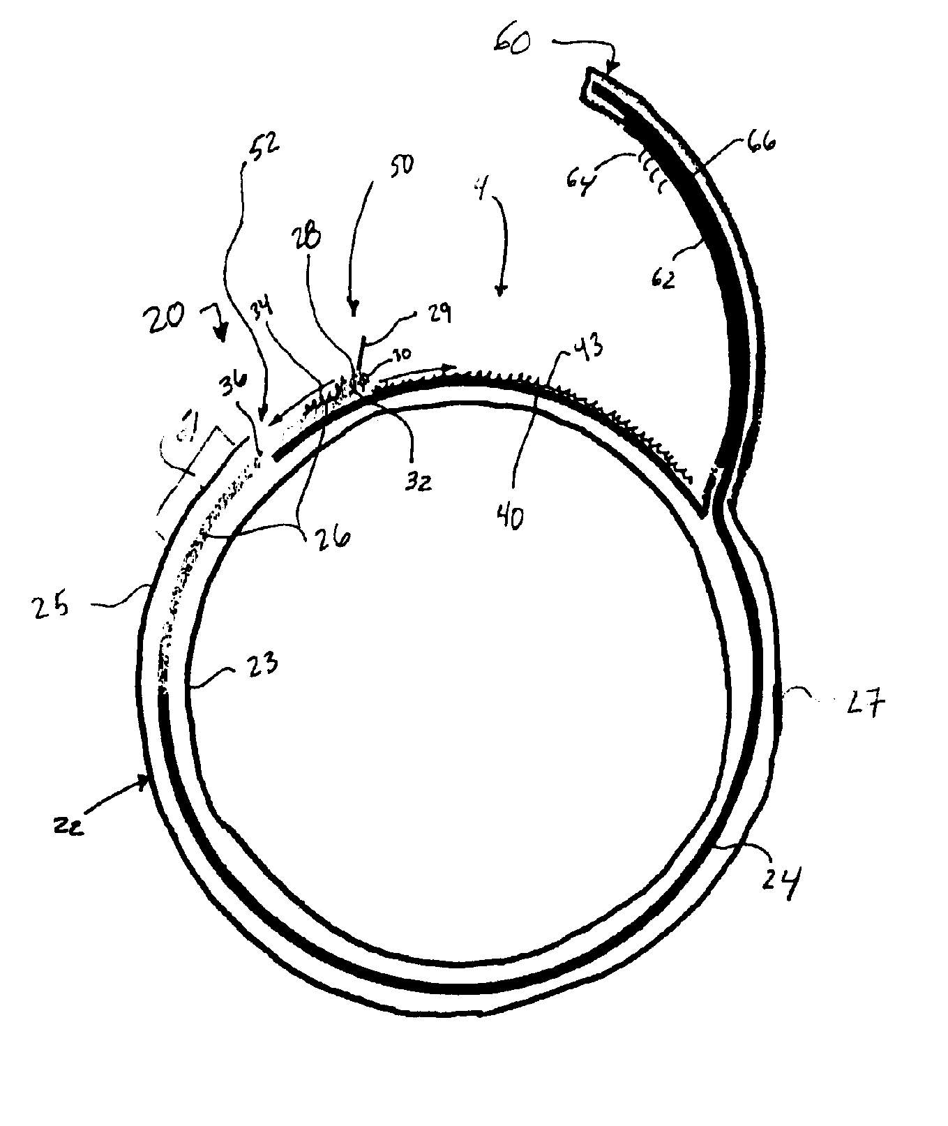
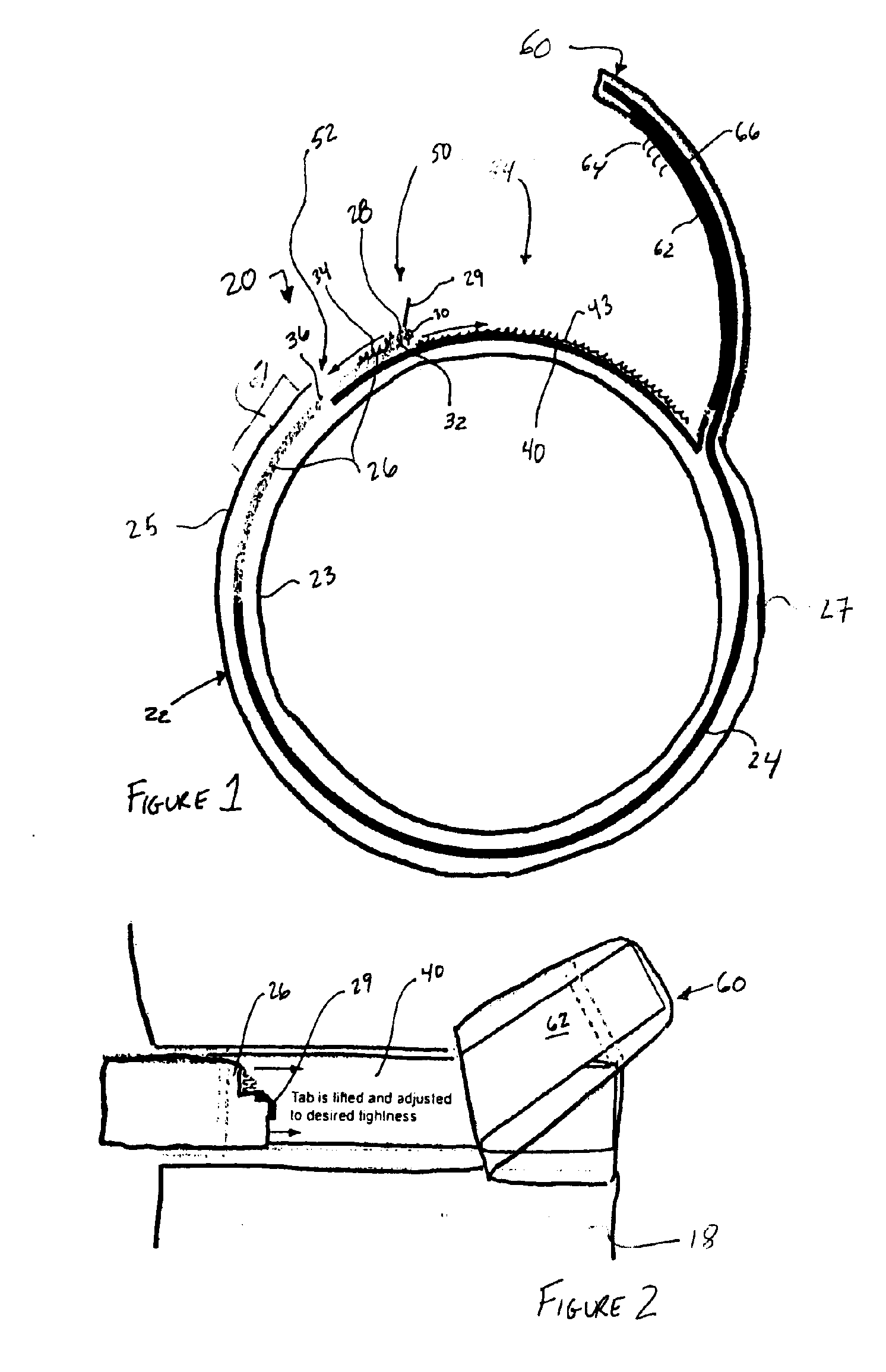
[0015]FIGS. 1 and 2 show an adjustable cuff system 20 of the present invention. In this embodiment, the garment 18 includes cuff system 20 and comprises a channel 22 formed by an inner wall 23 and an outer wall 25. The inner and outer walls 23 and 25, for example, may comprise the same or different layers of the garment. In one embodiment, for example, the channel 22 may be formed by folding over the outer layer of the garment and attaching it to itself, such as via stitching, bonding, welding, adhesion, or the like to make a “tube”. Another embodiment may form channel 22 by attaching using separate fabrics for inner wall 23 and outer wall 25 and connecting the layers using stitching, bonding, welding, adhesion, or the like to make a space between inner and outer walls 23 and 25.

[0016] The channel 22 may comprise an elastic or inelastic channel. The channel 22, for example, may be formed of an elastic or non-elastic material. The channel 22 may also comprise an elastic material atta...

second embodiment

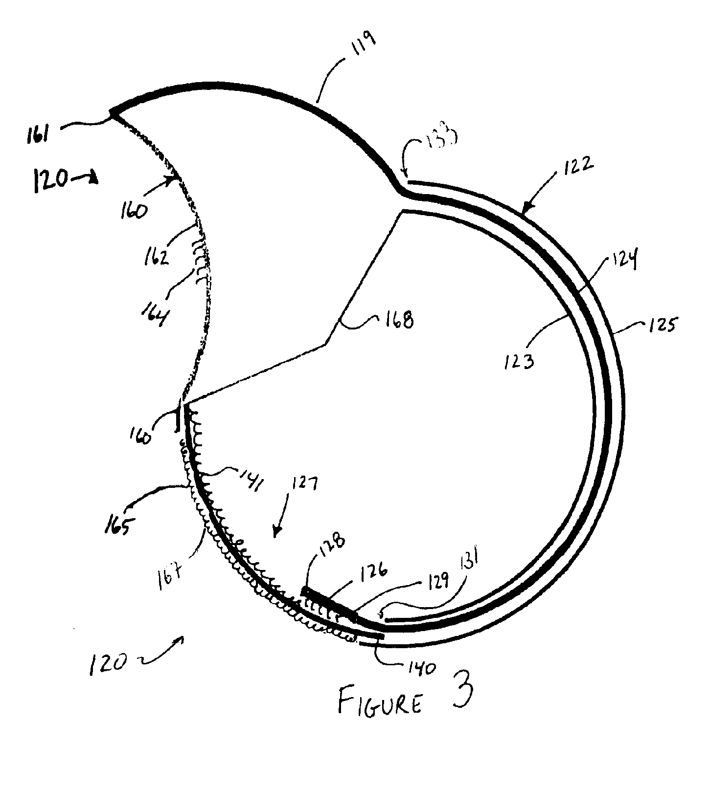
[0025]FIGS. 3-5 show an adjustable cuff system 120 of the present invention. As shown in FIG. 3, for example, the adjustable cuff system 120 comprises a channel 122 having an inner wall 123 and an outer wall 125. A portion of the inner wall 123 is open at a window 127. The window 127 is proximate a opening 131 defined by channel 122 out of which a first connector 126 extends into window 127. First connector 126 can be moved along window 127 to adjusting the size of the cuff and securing first connector 126 relative to a second connector 140. As described above, the channel 122 may be elastic, be partially elastic, or non-elastic.

[0026] The adjustable cuff system 120 further comprises a strip 124 extending at least partially through the channel 122. As described above, the strip 124 may at least partially comprise an elastic material or may comprise an entirely non-elastic material. The strip 124 comprises a first connector 126 at a first end 128 of the strip 124. The first connector...


PUM


Abstract

An adjustable cuff system for a garment includes a cuff having a cuff channel. A strip extends at least partially through the cuff channel and comprises a first connector attached to the strip. A second connector is attached to the cuff. The second connector is adapted to adjustably receive the first connector. The adjustable cuff system further comprises a tab extending from the cuff. The tab comprises a third connector adapted to secure the tab in a closed configuration.

Description

RELATED APPLICATION [0001] The present application claims the benefit of U.S. Provisional application No. 60 / 524,997, filed Nov. 24, 2003, titled the same, incorporated herein by reference.FIELD OF THE INVENTION [0002] The present invention is related to an adjustable cuff for garments and, more particularly, to a garment that has a cuff that is adjustable to a wearer's cuff size. BACKGROUND OF THE INVENTION [0003] Garments, such as, for example, jackets and the like, often employ adjustable cuffs to allow the cuff of the garment to be adjusted by a wearer. Commonly, cuffs include elastic extending around at least a portion of the perimeter and a tab that may be attached to the cuff at different positions to select the size of the cuff. The tab, for example, typically includes a hook portion that mates with an extended strip of loop material attached to the exterior of the cuff. [0004] When a wearer puts on a jacket, for example, the wearer extends his or her arm into the sleeve wit...

Claims


Application Information

Patent Timeline
IPC IPC(8): A41B7/00A41B11/12A41D27/10A41D27/16A41F1/06
CPCA41B11/125A41B2300/32A41F1/06A41D2300/32A41D27/10
Inventor BUSH TRENT E.
Owner TROY BUSH
Learn More