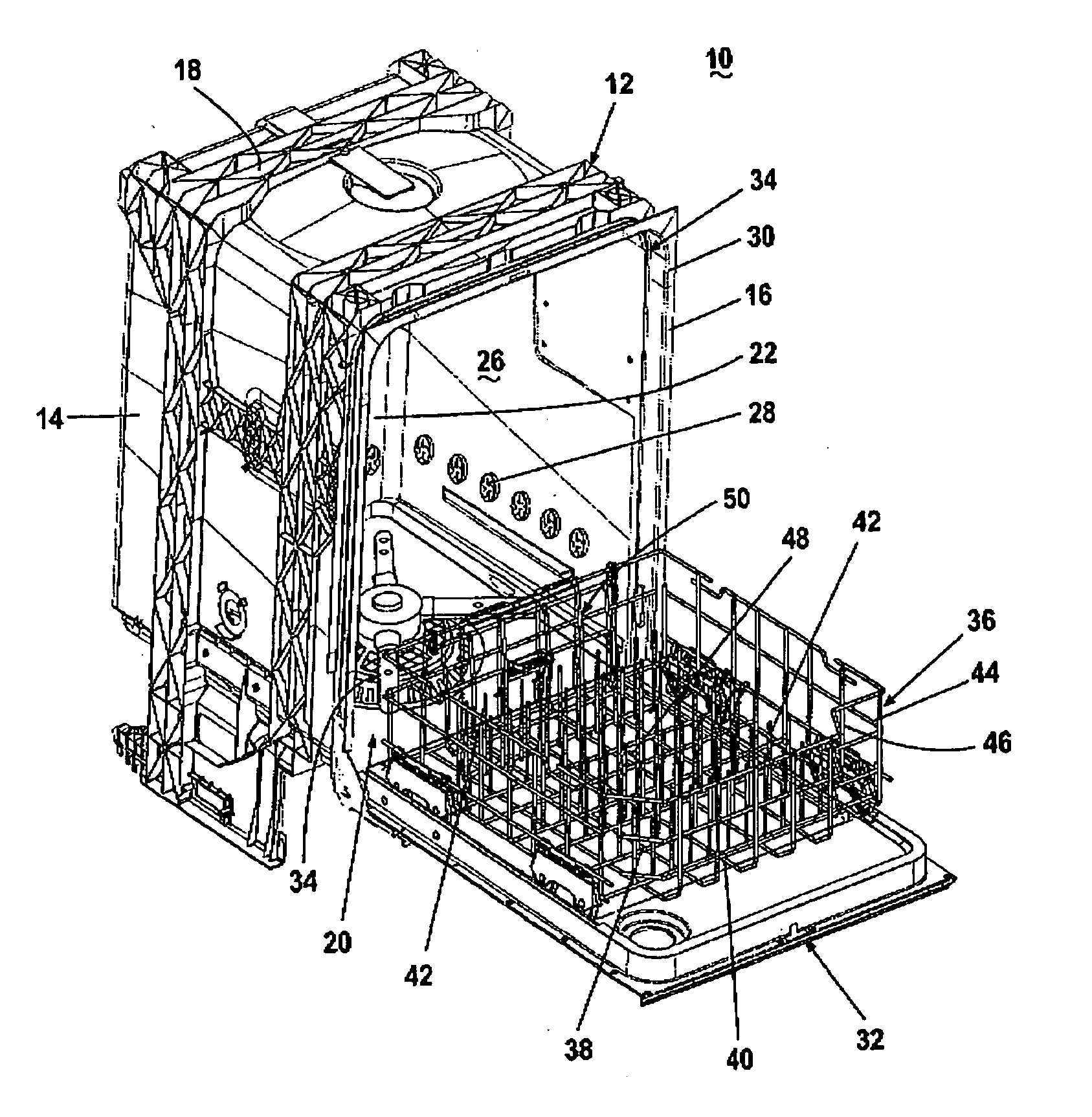
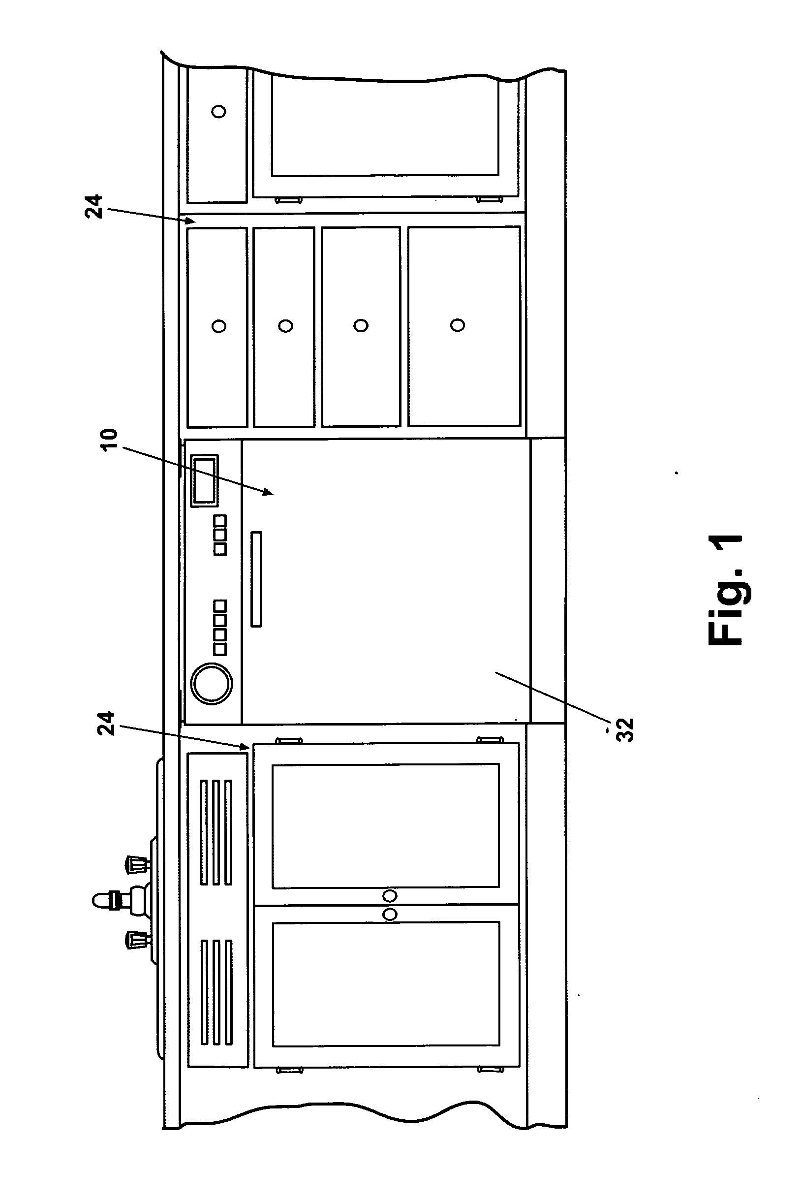
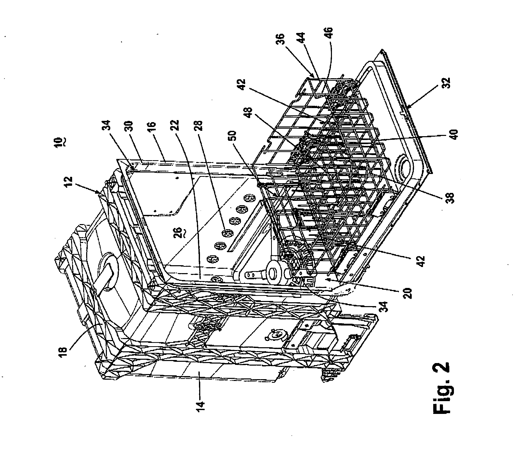
Dishwasher and adjustable rack
a dishwasher and adjustable technology, applied in the field of automatic dishwashers, can solve the problems of reducing the number of dishes that can be washed in a single load, reducing the number of dishes that cannot be washed, and the current dishwashing rack is not specifically designed
- Summary
- Abstract
- Description
- Claims
- Application Information
AI Technical Summary
Problems solved by technology
Method used
Image
Examples
second embodiment
[0056] The adjustable utensil carrier also eliminates the need to carefully position and balance large utensils against the vertically extending tines in the dishrack, and the potential that the utensil will shift out of the optimal cleaning position during washing. The adjustable utensil carrier also eliminates the problem that arises when a utensil is too tall for the vertically extending tines in the dishrack to maintain the utensil in the optimal position throughout the wash cycle, or when the utensils a side wall than is, too tall to fit between adjacent rows of tines, thereby preventing such a dish from being positioned at an angle relative to the vertical or in a vertical position. When the adjustable utensil carrier is not needed, it can be readily positioned or removed so that tableware and other utensils can be loaded into the dishwasher without interference from the adjustable utensil carrier. Finally, the adjustable utensil carrier is simple in design and operation, econ...
third embodiment
[0057]FIGS. 13A-16 illustrate the adjustable utensil carrier 120. As shown in FIGS. 13A-B, the utensil carrier 120 comprises a generally wire-frame construction comprising a planar array of regularly-spaced positioning tines 122 adapted through right-angle bends to form, with suitable cross members 126, a floor latticework 124. The positioning tines 122 extend generally orthogonally upwardly from the floor latticework 124 to form a support wall for supporting a cooking utensil in the optimal cleaning position.
[0058]FIGS. 14-16 illustrate a detent latch 128 which is used to adjust the positioning of the utensil carrier 120. The detent latch 128 comprises an adjustment lever 130 and a detent housing 132. The adjustment lever 130 is a generally elongated, irregularly shaped lever-like body terminating at one end in a pivot shaft 134 extending outwardly from an outer surface orthogonal to the plane of the adjustment lever 130. The pivot shaft 134 comprises a C-shaped, semi-annular wall ...
fourth embodiment
[0066]FIGS. 17A-18 show an adjustable utensil carrier 180 comprising an adjustable rack 181 and a detent latch 192. The adjustable rack 181 comprises a planar array of parallel positioning tines 182 rigidly attached to a pivot wire 184 and adapted to extend orthogonally therefrom into the utensil holding space 48 to form a support wall for supporting a cooking utensil in the optimal cleaning position. The array of positioning tines 182 terminates with a locking tine 186 having an attachment portion 185 transitioning to an offset portion 188 which terminates in an engagement portion 190 offset from and parallel to the attachment portion 185 and the remaining positioning tines 182 in the array.
[0067] The detent latch 192 comprises a somewhat oval-shaped mounting plate 194 having an obverse face 196 and a reverse face 198. The reverse face 198 is adapted for cooperative juxtaposition with the perimeter latticework 38. A wire detent 206 extends through one end of the mounting plate 194 ...
PUM
 Abstract
Description
Claims
Application Information
 - R&D
- Intellectual Property
- Life Sciences
- Materials
- Tech Scout
- Unparalleled Data Quality
- Higher Quality Content
- 60% Fewer Hallucinations
Browse by: Latest US Patents, China's latest patents, Technical Efficacy Thesaurus, Application Domain, Technology Topic, Popular Technical Reports.
© 2025 PatSnap. All rights reserved.Legal|Privacy policy|Modern Slavery Act Transparency Statement|Sitemap|About US| Contact US: help@patsnap.com


