
Ventilation mattress

a technology of ventilation mattress and mattress, applied in the field of mattresses, can solve the problems of user's body, seat or bed mattress becoming hot within a short time, and its cooling effect is gradually reduced, so as to improve the flexibility and ventilation of the ventilation mattress

Inactive Publication Date: 2005-04-28
WU HSIANG LING
View PDF6 Cites 119 Cited by
  • Summary
  • Abstract
  • Description
  • Claims
  • Application Information

AI Technical Summary

Benefits of technology

"The present invention is a ventilation mattress that has an outer bag filled with a fabric stuffing member for ventilation. The fabric stuffing member is made of interwoven spandex fibers with open spaces for air circulation. A flexible pad is added at the bottom of the fabric stuffing member to improve flexibility and ventilation. High-performance fans are installed to draw air into the outer bag for circulation. Membrane type pressure switches are provided inside the outer bag to turn on or off the high-performance fans when the user is sitting on the mattress. The invention can also use electric cooling fans or electric fans with electric heater means. Additionally, semiconductor cooler chips can be used with the high-performance fans."

Problems solved by technology

However, a cooling mattress absorbs heat energy from the surrounding and the user's body when in use, its cooling effect is gradually diminished with the time in which the user sits or lies on the cooling mattress.
However, when sitting or lying on a seat or bed mattress of this design, the user's body will block the open spaces, and the seat or bed mattress becomes hot within a short time.
This design of seat mattress still has drawbacks.
Because currents of air are guided in a particular direction, the ventilation effect is limited.
Further, because the inner layer is a hard member, it is not comfortable to sit on the seat mattress.

Method used


Image

  • Ventilation mattress
  • Ventilation mattress
  • Ventilation mattress

Examples


Embodiment Construction

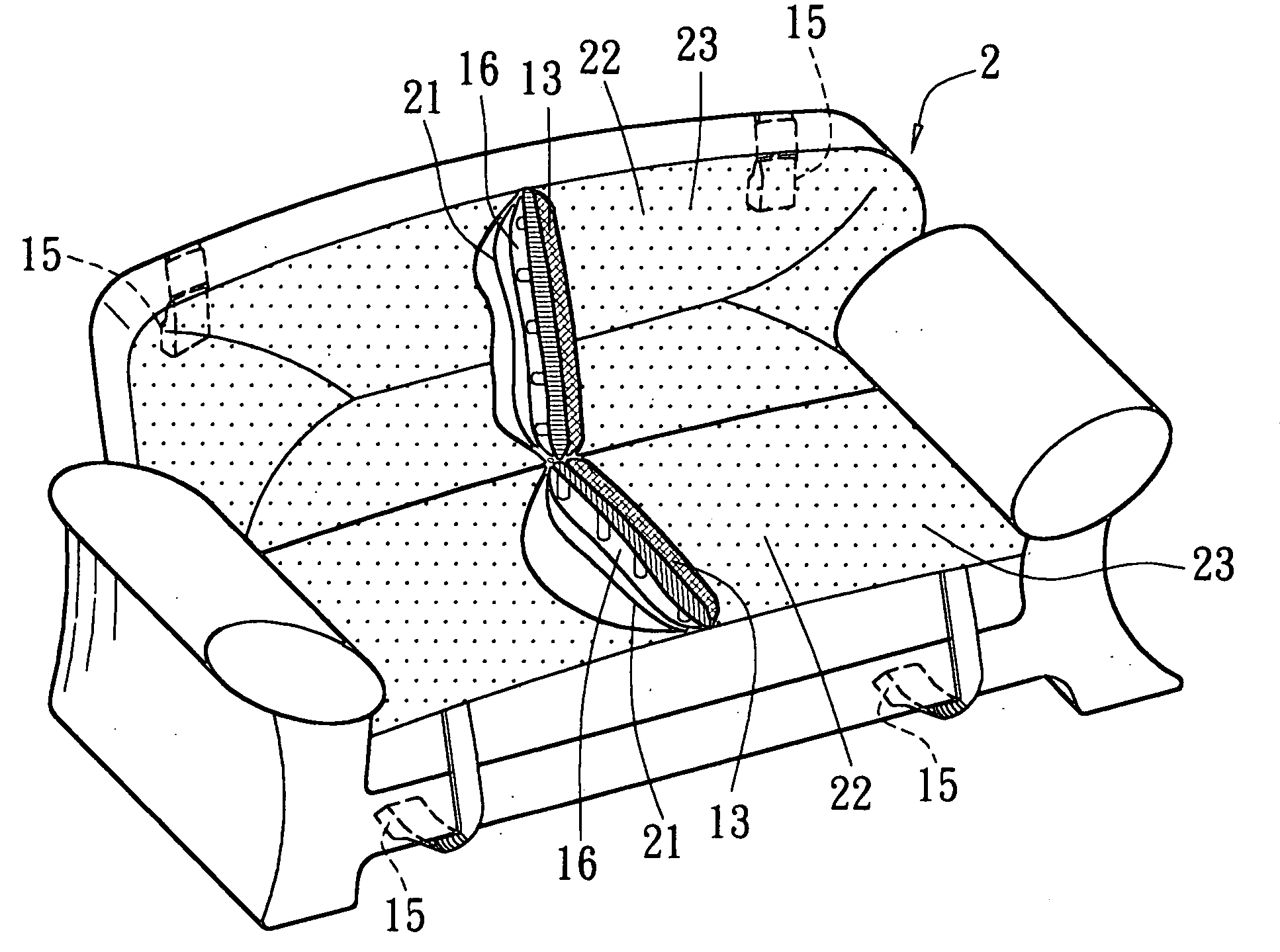
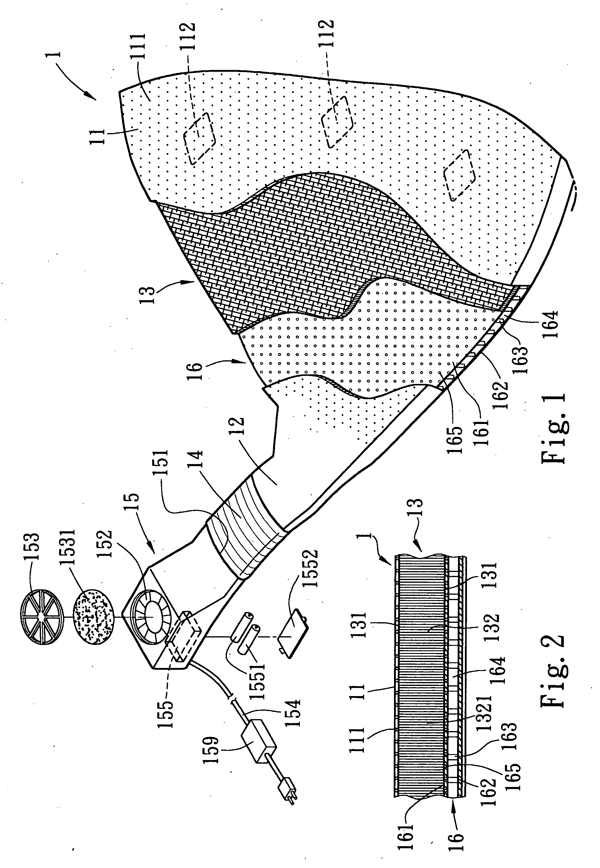
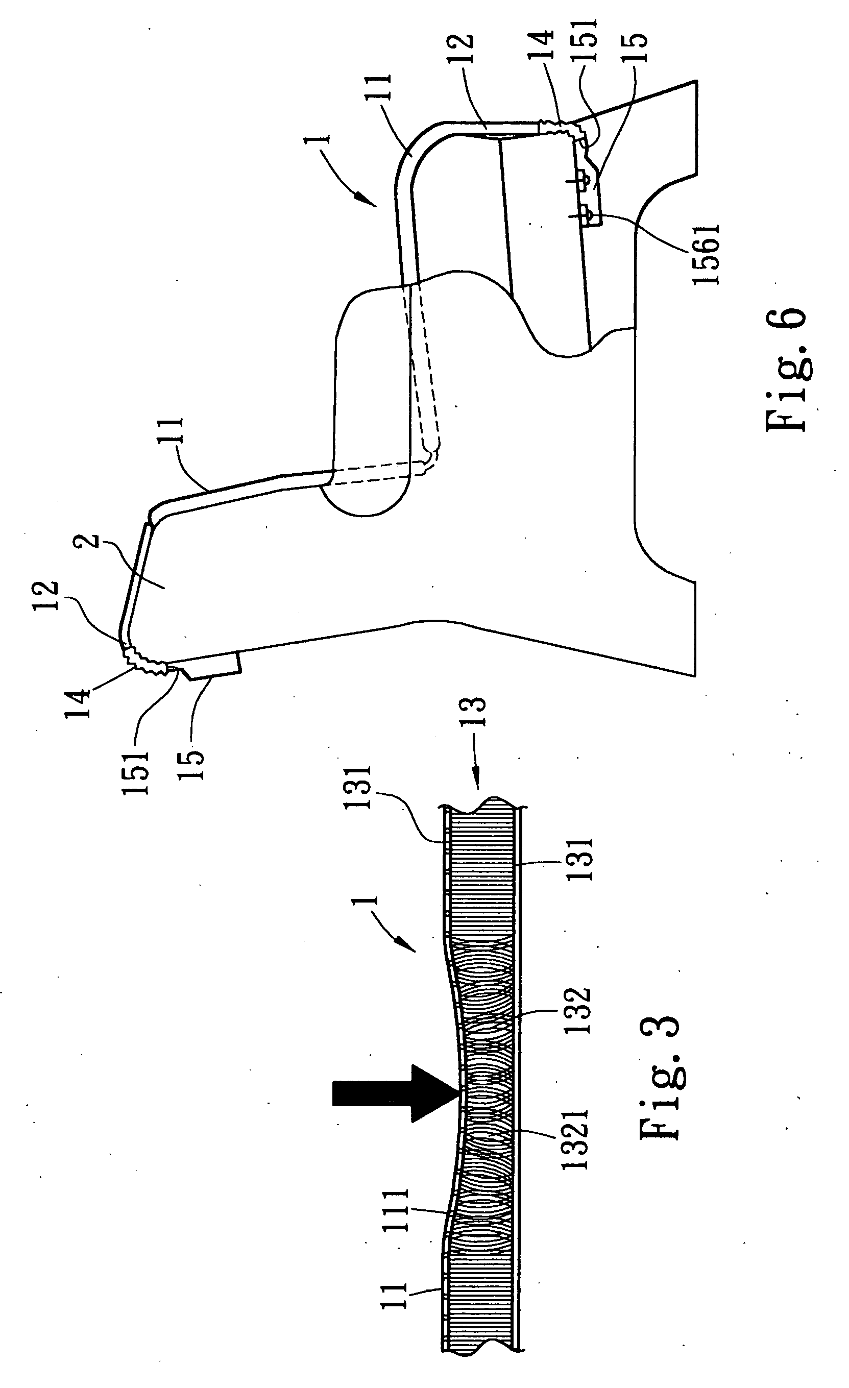
[0031] Referring to FIGS. 1˜4, a ventilation mattress 1 is shown comprising an outer bag 11, a fabric stuffing member 13 put in the outer bag 11, a flexible pad 16 provided at the bottom side of the fabric stuffing member 13 inside the outer bag 11, an air inlet 12 formed in one side of the outer bag 11, a flexible tube 14 extended from the air inlet 12, and a high-performance fan 15 provided at one end of the flexible tube 14 remote from the air inlet 12. The fabric stuffing member 13 is three-dimensional device formed of interwoven spandex fibers 132, having open spaces 1321 in it for ventilation. The outer bag 11 is formed of top and bottom fabric sheet layers 131, having small air vents 111 in the top side (top fabric sheet layer). The flexible pad 16 comprises a top cover layer 161, a bottom cover layer 162, a plurality of springy support members 163 connected between the top cover layer 161 and the bottom cover layer 162, an air passage 164 defined in between the top cover lay...


PUM


Abstract

A ventilation mattress is constructed to include an outer bag, the outer bag having air vents in a top fabric sheet layer thereof and an air inlet, a flexible tube connected to the air inlet of the outer bag, an electric fan installed in the flexible tube and adapted to draw currents of air into the inside of the outer bag, a fabric stuffing member formed of interwoven spandex fibers and stuffed in the outer bag, a flexible pad provided at the bottom side of the fabric stuffing member, the flexible pad having springy support members connected between top and bottom cover layers thereof for enabling air to circulate through the flexible pad between the air inlet and the air vents at the outer bag.

Description

BACKGROUND OF THE INVENTION [0001] 1. Field of the Invention [0002] The present invention relates to a mattress and, more particularly, to a ventilation mattress, which uses an electric fan to provide currents of air through air vents in the top layer of the outer covering for ventilation. The ventilation mattress can be made in any of a variety of forms for use as a seat mattress, sofa mattress, or bed mattress. [0003] 2. Description of the Related Art [0004] Straws and bamboo strips are commonly used for making cooling mattresses for the advantage of being highly ventilative. Lying or sitting on a cooling mattress during a hot weather is comfortable at the initial stage. However, a cooling mattress absorbs heat energy from the surrounding and the user's body when in use, its cooling effect is gradually diminished with the time in which the user sits or lies on the cooling mattress. [0005] There are also known seat and bed mattresses formed of strings of ball or block elements. The...

Claims


Application Information

Patent Timeline
Patent Type & Authority Applications(United States)
IPC IPC(8): A47C7/74A47C21/04A47C27/00
CPCA47C7/744A47C7/748A47C31/116A47C21/048A47C27/007A47C21/044
Inventor WU, HSIANG-LING
Owner WU HSIANG LING
Learn More