Screw-belt advancing mechanism for a screw driving gun

a screw-retaining belt and screw technology, applied in the field of screw-retaining belt advancing mechanism of screw-retaining belt unit, can solve the problems of inconvenient and laborious pulling of the screw-retaining belt uni

Active Publication Date: 2005-04-07
LIN CHAO WEI
View PDF2 Cites 18 Cited by
  • Summary
  • Abstract
  • Description
  • Claims
  • Application Information

AI Technical Summary

Problems solved by technology

The aforesaid conventional screw driving gun 2 is disadvantageous in that it is inconvenient and laborious to pull the screw-retaining belt unit 3 manually in order to align a selected one of the screws 31 with the driving shaft 21.

Method used


Image

  • Screw-belt advancing mechanism for a screw driving gun
  • Screw-belt advancing mechanism for a screw driving gun
  • Screw-belt advancing mechanism for a screw driving gun

Examples


Embodiment Construction

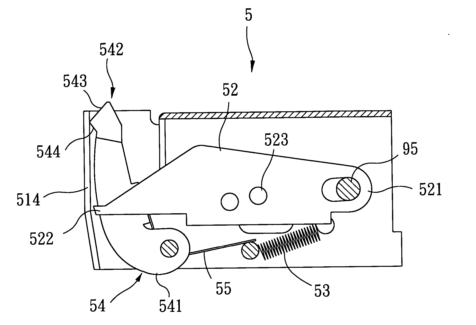
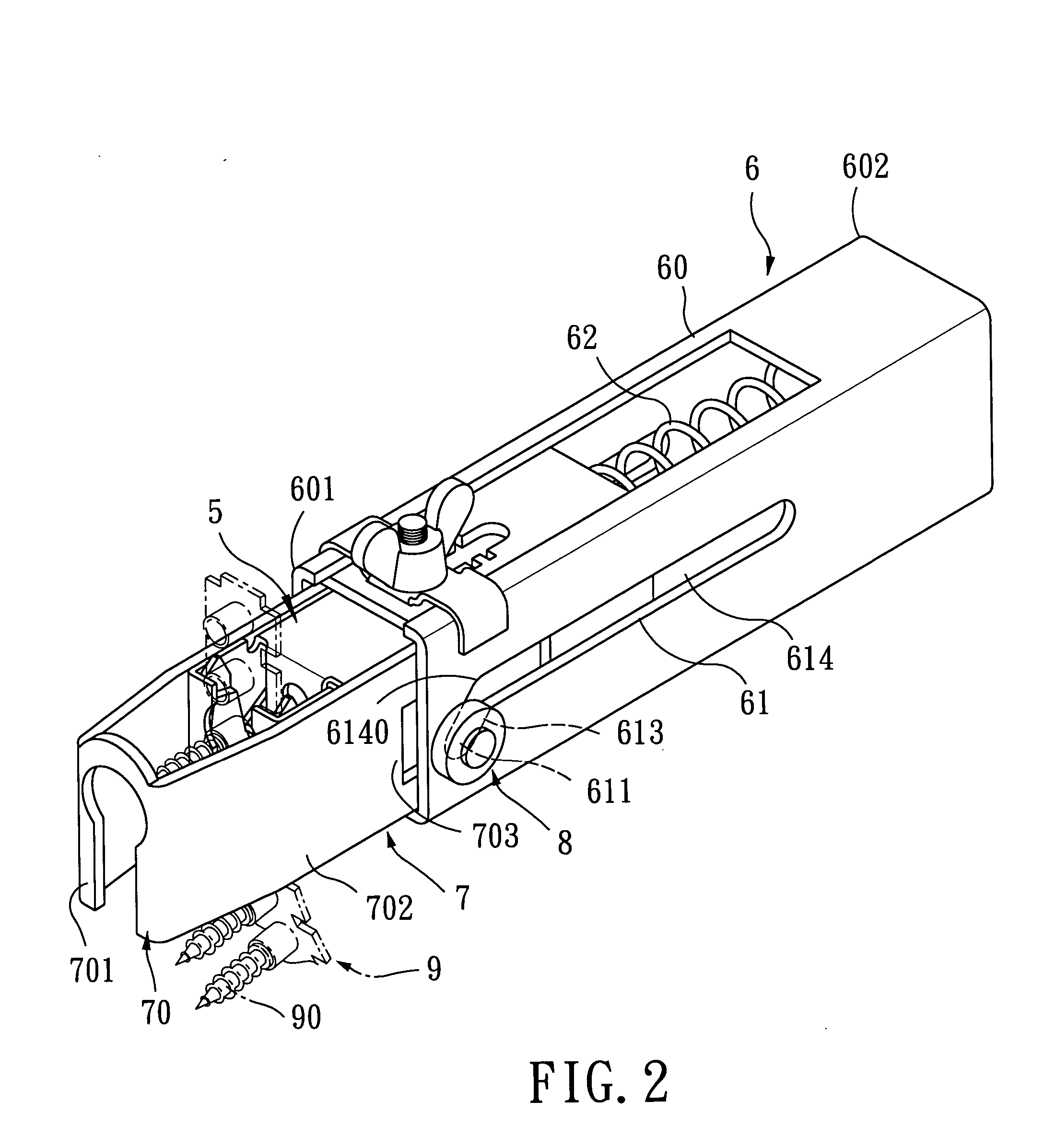
[0017] Referring to FIGS. 2 to 5, the preferred embodiment of a screw-belt advancing mechanism 5 according to the present invention is used to advancing a screw-retaining belt 9 on a screw driving gun (not shown), and is shown to include a barrel unit 6, a sliding unit 7, an urging member 62, a spring-biased positioning member 54, a pivot pin 95, and a spring-biased lifting member 52.

[0018] As illustrated, the screw-retaining belt 9 supports detachably a plurality of screws 90 thereon, and has a plurality of engaging holes 91, each of which is disposed between adjacent two of the screws 90.

[0019] The barrel unit 6 includes a casing 60 that has a front end 601 and a rear end 602 adapted to be connected to the screw driving gun (not shown), that is adapted to receive a driving shaft 65 therein, and that defines a longitudinal direction.

[0020] The sliding unit 7 is connected telescopically to the front end 601 of the casing 60, is movable in the longitudinal direction relative to th...


PUM


Abstract

A screw-belt advancing mechanism of a screw driving gun includes a barrel unit, a sliding unit connected telescopically to the barrel unit and movable relative thereto between extended and retracted positions, a pivot pin mounted on the sliding unit, and a spring-biased lifting member to engage releasably a screw-retaining belt fed into the sliding unit. The lifting member is pivoted to the pivot pin, and is associated with the sliding unit in such a manner that the lifting member is moved toward the barrel unit and pivots about the pivot pin in a first direction so as to push the screw-retaining belt to a desired position, in which, a selected screw on the screw-retaining belt is aligned with a driving shaft in the barrel unit when the sliding unit slides from the extended position to the retracted position.

Description

BACKGROUND OF THE INVENTION [0001] 1. Field of the Invention [0002] The present invention relates to a screw driving gun, more particularly to a screw-belt advancing mechanism for a screw driving gun. [0003] 2. Description of the Related Art [0004] Referring to FIG. 1, a conventional screw driving gun 2 (illustrated in phantom lines) generally includes a driving shaft 21, a belt-retaining mechanism 1, and a screw-retaining belt unit 3. The screw-retaining belt unit 3 includes a belt body 30, a plurality of screw 31 retained releasably on the belt body 30, and a plurality of engaging holes 32, each of which is disposed between adjacent two of the screws 31. [0005] The belt-retaining mechanism 1 includes a sliding unit 10, a barrel unit 22, and a belt-retaining member 12. The barrel unit 22 receives the driving shaft 21 therein, and has a rear end connected to the screw driving gun 2, and a front end opposite to the rear end. The sliding unit 10 is connected telescopically to the fron...

Claims


Application Information

Patent Timeline
Patent Type & Authority Applications(United States)
IPC IPC(8): B25B23/04
CPCB25B23/045
Inventor LIN, CHAO-WEI
Owner LIN CHAO WEI
Why Eureka
Try Eureka