
Systems, methods and computer program products for assessing the health of an electric motor

Active Publication Date: 2005-02-10
GENERAL ELECTRIC CO
View PDF7 Cites 34 Cited by
  • Summary
  • Abstract
  • Description
  • Claims
  • Application Information

AI Technical Summary

Benefits of technology

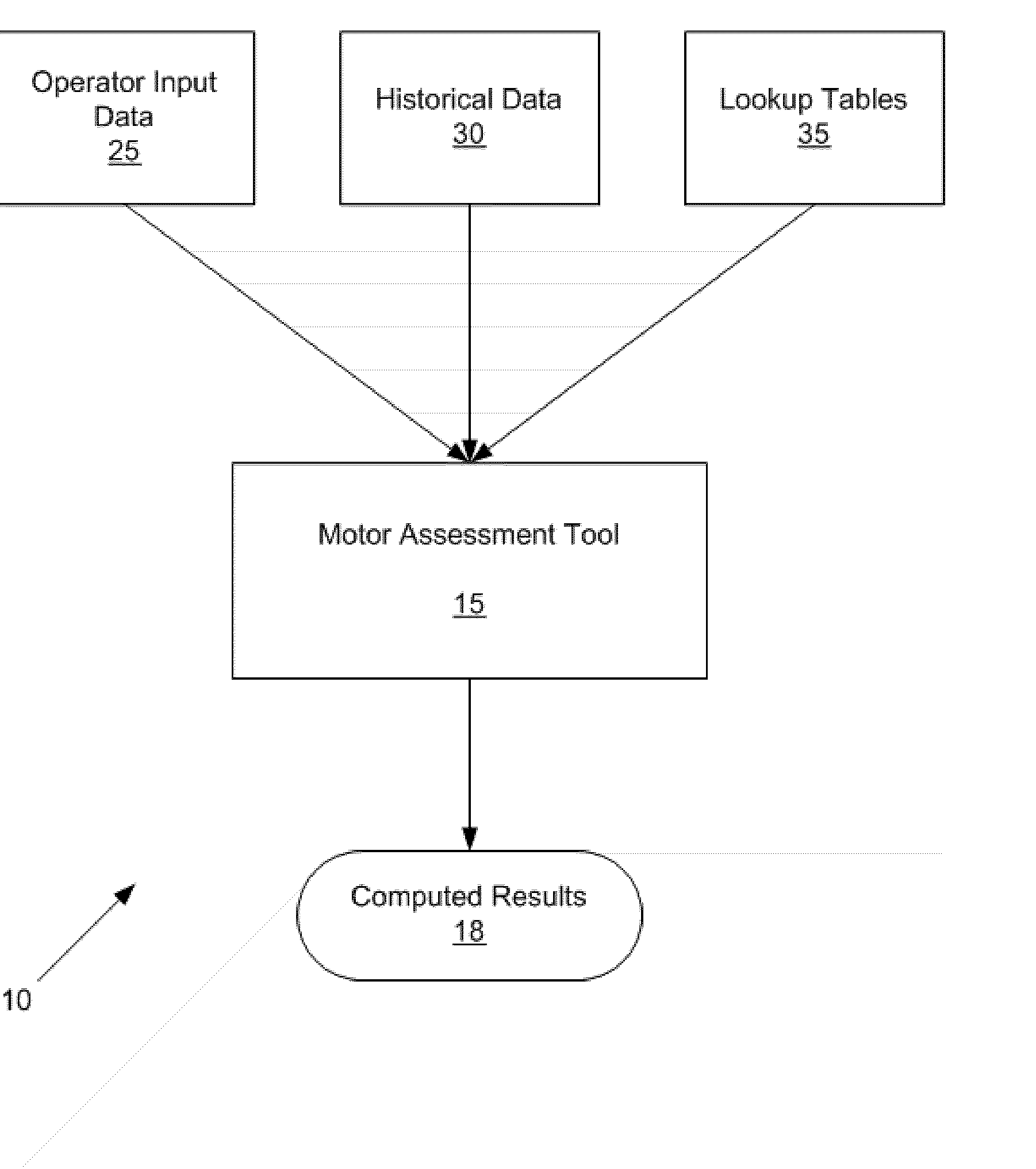
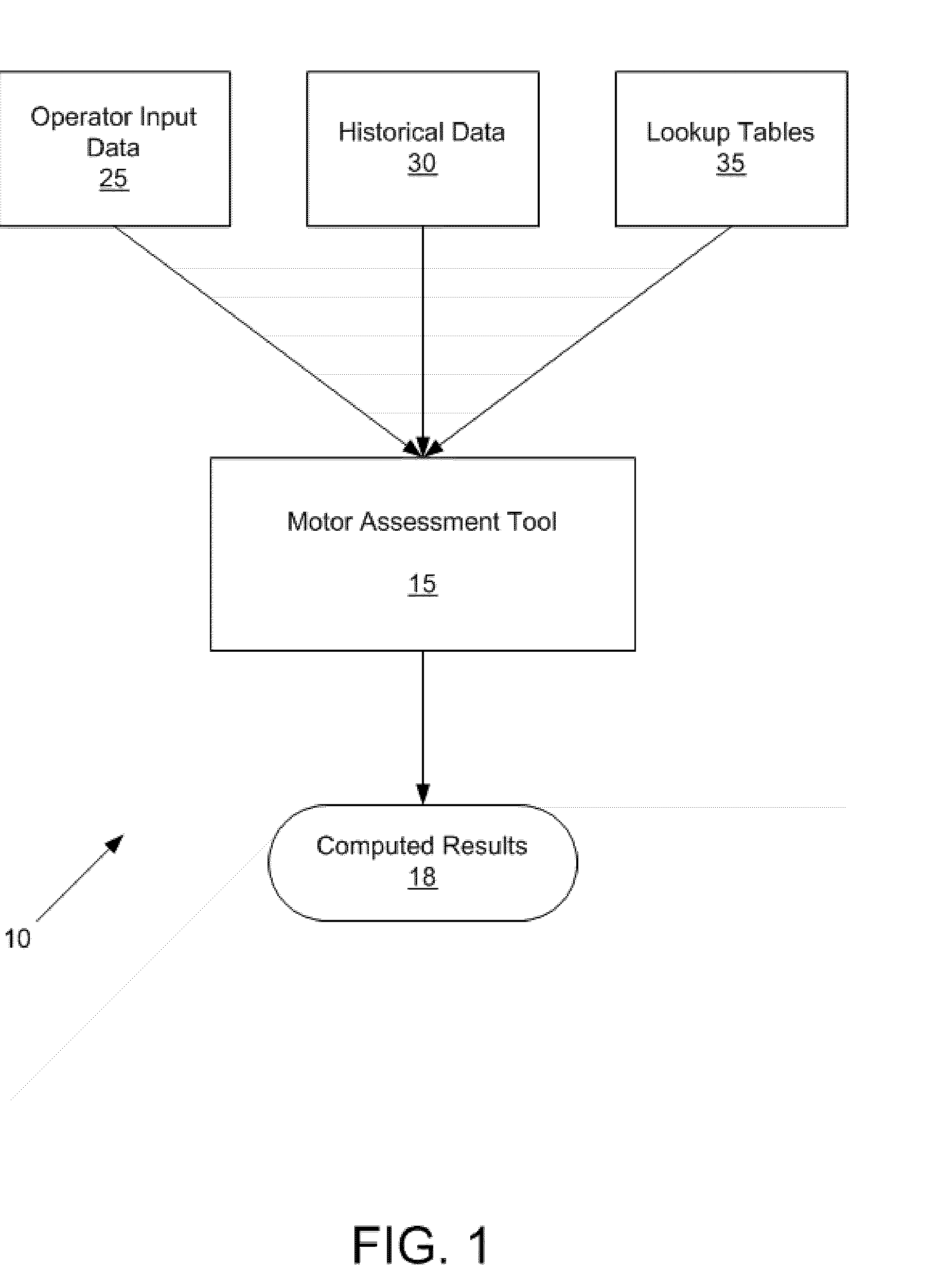
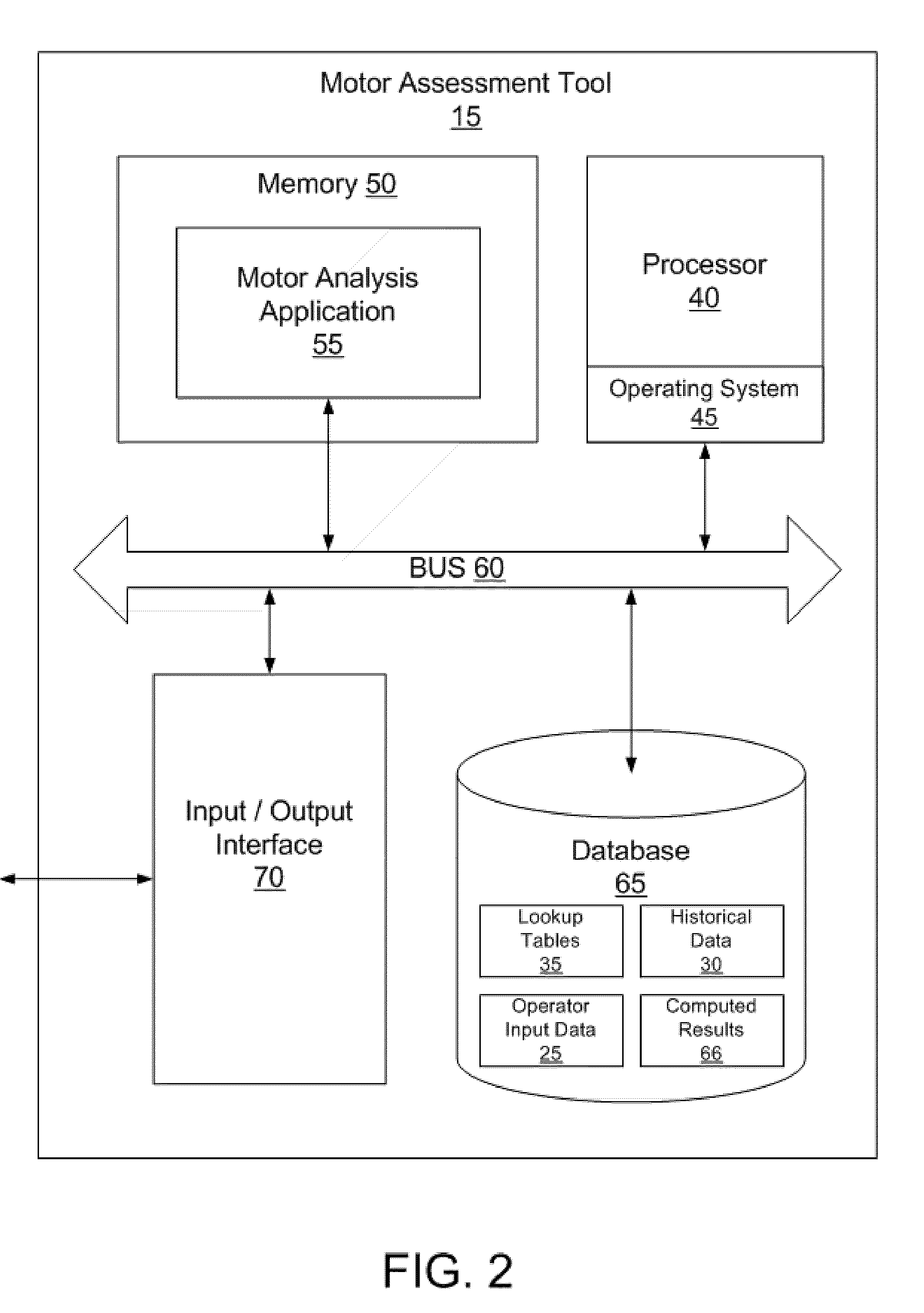
To generate such results, the motor assessment tool collects information from multiple sources, including operator input data, historical data, and lookup tables. Based on this information the motor assessment tool estimates the remaining usef

Problems solved by technology

Although electric motors are rugged and reliable electromechanical energy conversion devices, they are subject to failure under mis-operation, severe operating conditions, hostile environments, and aging.
In industries that require the motor to be operated under hostile conditions and environment, such as mining or pulp and paper industries, the annual failure rate can be much higher.
Since motor failure has a potential for substantial financial loss, the demand for motor protection has increased, which has driven many researchers in industry and academia to explore new technologies in condition monitoring of electric machines and electrically driven equipment.
According to industry standards, almost one half of the total failures for electric motors are bearing-related.
Additionally, one third or more failures are typically related to the winding insulation and core iron.
Unfortunately, however, greater variations exist in AC motors greater than 2300V.
For instance, whereas bearing failures are more prevalent in induction motors due to the presence of a large population of rolling element bearings, in AC motors greater than 2300V AC stator failures replace bearing failures as the dominant problem.
However, these systems cannot provide an immediate assessment on the condition of a motor if, for instance, a customer wishes to establish a maintenance / shared risk agreement with a electric motor provider in terms of residual life estimates.

Method used


Image

  • Systems, methods and computer program products for assessing the health of an electric motor
  • Systems, methods and computer program products for assessing the health of an electric motor
  • Systems, methods and computer program products for assessing the health of an electric motor

Examples


Embodiment Construction

The present invention now will be described more fully hereinafter with reference to the accompanying drawings, in which preferred embodiments of the invention are shown. This invention may, however, be embodied in many different forms and should not be construed as limited to the embodiments set forth herein; rather, these embodiments are provided so that this disclosure will be thorough and complete, and will fully convey the scope of the invention to those skilled in the art. Like numbers refer to like elements throughout.

The present invention is described below with reference to block diagrams and flowchart illustrations of methods, apparatuses (i.e., systems) and computer program products according to an embodiment of the invention. It will be understood that each block of the block diagrams and flowchart illustrations, and combinations of blocks in the block diagrams and flowchart illustrations, respectively, can be implemented by computer program instructions. These comput...


PUM


Abstract

Systems, methods and computer program products calculate the life remaining in a machine, such as an electric motor, or the life remaining in individual components within a machine. Life remaining calculations are based on information collected from multiple sources, including operator input data, historical data, and lookup tables. Using this information the remaining useful life of the machine is calculated based on quantitative data, standard design life limits and on reliability analysis such that continuous historical parameter data is not required to analyze or assess the life of the machine.

Description

BACKGROUND OF INVENTION 1. Field of the Invention The present invention relates to electric motors, and more particularly, to systems, methods and computer program products for assessing the health of an electric motor without requiring access to extensive historical asset management and historical sensor data. 2. Background of the Invention Although electric motors are rugged and reliable electromechanical energy conversion devices, they are subject to failure under mis-operation, severe operating conditions, hostile environments, and aging. The average annual failure rate of large electric machines is estimated to be at least three percent. In industries that require the motor to be operated under hostile conditions and environment, such as mining or pulp and paper industries, the annual failure rate can be much higher. Since motor failure has a potential for substantial financial loss, the demand for motor protection has increased, which has driven many researchers in industr...

Claims


Application Information

Patent Timeline
IPC IPC(8): G05B23/02G06F11/00G06F11/30
CPCG06F11/008G05B23/0283
Inventor HOUSE, MICHAEL BRYNNFLICKINGER, GREGORY LEEPAPPU, NARASIMHA MURTHY
Owner GENERAL ELECTRIC CO
Learn More