Composite vehicle driveshaft with crash collapse system

a technology of drive shaft and composite vehicle, which is applied in the direction of shaft and bearings, mechanical equipment, couplings, etc., can solve the problem of increasing the risk of part wear at the interface(s)

Active Publication Date: 2022-07-12
COMPOSITE DRIVELINES LLC
View PDF24 Cites 2 Cited by
  • Summary
  • Abstract
  • Description
  • Claims
  • Application Information

AI Technical Summary

Benefits of technology

[0005]In accordance with a first aspect of the invention, a composite vehicle driveshaft is provided that allows for a controlled longitudinal collapse by facilitating telescopic movement of various components with respect to each other during a crash event in which the composite vehicle driveshaft is subjected to compressive or longitudinal pushing forces that overcome corresponding component longitudinal fixation forces between those components.
[0006]In accordance with another aspect of the invention, the composite vehicle driveshaft includes a composite tube that has opposed tube ends, and a tube sidewall that extends longitudinally or axially between the tube ends. A crash collapse system can reduce a length of the composite vehicle driveshaft during a crash event that applies sufficient force to the driveshaft. The crash collapse system may include a stub end assembly arranged at an end of the composite tube. The stub end assembly includes a stub shaft that extends longitudinally beyond and is locked into rotational unison with the end of the composite tube. The crash collapse system is configured to longitudinally or axially fix the stub shaft relative to the composite tube until a longitudinal pushing force of sufficient magnitude, which corresponds to a minimum breakaway or collapse force value, is applied against the composite vehicle driveshaft. When this happens, the crash collapse system allows the stub shaft to longitudinally retract at least partially into the composite tube.
[0008]In accordance with another aspect of the invention, the sleeve may define a sleeve inner circumferential surface with splines that define a sleeve splined segment. The stub shaft may include a stub shaft base with an outer circumferential surface that has splines that define a stub shaft base splined segment. The splines of the sleeve and stub shaft may be, for example, straight or helical and correspond to each other to allow their splined engagement. The sleeve and stub shaft base splined segments engage each other to lock them into rotational unison with each other while allowing the telescopic movement of the collapsible joint during the crash event. The engaged sleeve and stub shaft base segments may provide an interference fit between each other at the collapsible joint to longitudinally or axially fix the stub shaft with respect to the composite tube when in the extended state. The interference fit between the stub shaft base and the sleeve may be formed by a press-fit and / or a thermal shrink-fit procedure. The interference fit may also be applied to the splined interfaces of the stub shaft and the sleeve to avoid any backlash between teeth / splines of the stub shaft base and sleeve. Without such interference fit, the corresponding shoulder / collar surfaces of the stub shaft and the sleeve could experience backlash that would increase the risk of part wear at their interface(s).
[0009]In accordance with another aspect of the invention, the stub shaft base may include a locating collar that is housed in a guide chamber of the sleeve. The locating collar may be inboard of the splines of the stub shaft base splined segment. A shoulder of the sleeve may extend radially into the sleeve cavity between the guide chamber and splined chamber and may provide a mechanical stop against which the locating collar abuts to prevent extension-type withdrawal of the stub shaft through an outer or front end of the sleeve. A seal, such as an o-ring, may be arranged at the sleeve outer end between the sleeve and the stub shaft to create a barrier between the front or outer end of the splined chamber and the outside. The o-ring may be seated in a groove that extends into at least one of an inner circumferential surface of the sleeve and an outer circumferential surface of the stub shaft base.

Problems solved by technology

Without such interference fit, the corresponding shoulder / collar surfaces of the stub shaft and the sleeve could experience backlash that would increase the risk of part wear at their interface(s).

Method used


Image

  • Composite vehicle driveshaft with crash collapse system
  • Composite vehicle driveshaft with crash collapse system
  • Composite vehicle driveshaft with crash collapse system

Examples


Embodiment Construction

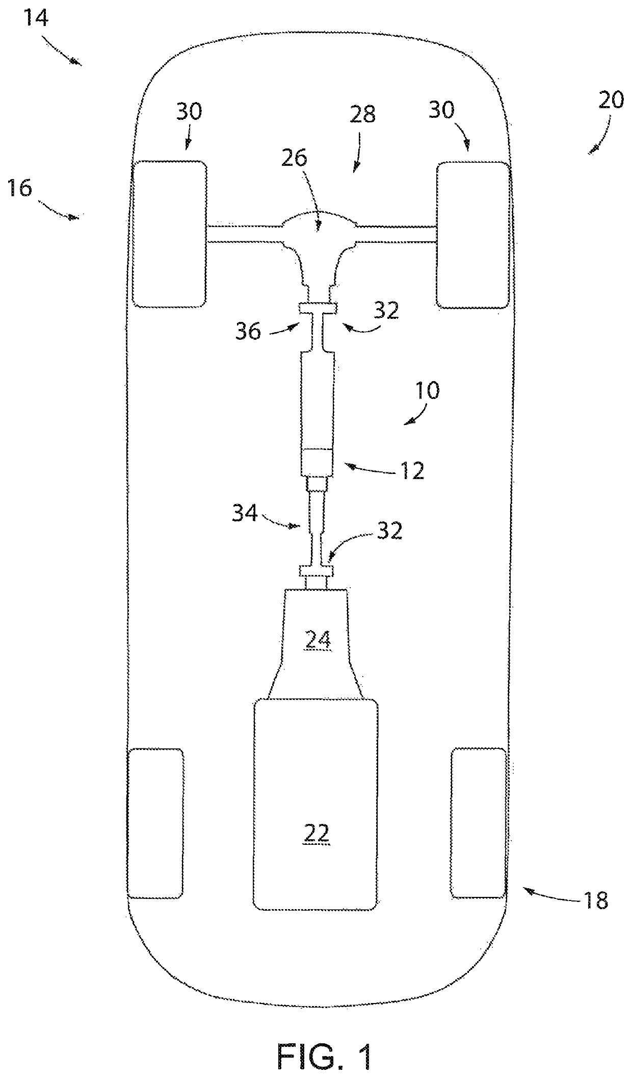
[0022]Referring now to the drawings and initially to FIG. 1, a composite vehicle driveshaft 10 with a crash collapse system 12 is shown implemented in a vehicle 14, represented here as an automobile 16. Automobile 16 has front and rear ends 18, 20 and a powertrain that includes a prime mover such as engine 22. Transmission 24 receives power from the engine 22 and delivers it downstream through the composite vehicle driveshaft 10 to a differential 26 that delivers the power through a drive axle 28 to a pair of drive wheels 30. A pair of CV (constant velocity) joints 32 is shown respectively connecting the driveshaft front end 34 to the transmission 24 and the driveshaft rear end 36 to the differential 26. It is understood that instead of the transmission 24 and differential 28, the composite vehicle driveshaft 10 may instead transmit power from the engine 22 to a transaxle that combines a transmission and drive axle. Regardless of the particular configuration of automobile 16, the cr...


PUM


Abstract

A composite vehicle driveshaft is provided with a crash collapse system that allows for a controlled longitudinal collapse of the driveshaft by facilitating telescopic movement of various components with respect to each other during a crash event. The crash collapse system may include a collapsible joint with a sleeve that is concentrically bonded in an end of a composite tube and a stub end assembly that is spline-engaged and interference fit within the sleeve, such as by way of a press-fit and / or a thermal shrink-fit procedure. This relationship may rotationally lock and axially fix the stub end assembly to the sleeve unless, during a crash event, the composite vehicle driveshaft experiences a compression or push-type force that exceeds a minimum breakaway or collapse force value that longitudinally and telescopically collapses the composite vehicle driveshaft.

Description

CROSS-REFERENCE TO RELATED APPLICATIONS[0001]This application claims the benefit of U.S. Provisional Patent Application No. 62 / 652,011, filed Apr. 3, 2018, hereby incorporated by reference in its entirety.FIELD OF THE INVENTION[0002]The invention relates generally to vehicle propel shafts or driveshafts that are made from composite materials. The invention additionally relates to a composite vehicle driveshaft with a crash collapse system that allows the driveshaft to collapse in a controlled manner during a crash.BACKGROUND OF THE INVENTION[0003]Composite driveshafts are available, which have resulted from efforts to provide weight reduction for rotating assemblies. Applications of composite driveshafts include stationary power transmission applications, such as transmitting torque for operating pumps and other industrial-type uses.[0004]Vehicles typically have driveshafts, but composite driveshafts have not been widely implemented for vehicle use. Numerous substantial challenges a...

Claims


Application Information

Patent Timeline
Patent Type & Authority Patents(United States)
IPC IPC(8): F16C3/03F16D3/06F16C3/02
CPCF16C3/03F16C3/026F16D3/06F16C2326/06Y10T403/473Y10T403/7033F16D1/068F16D2001/103F16D1/0858F16D2250/0069
Inventor DORMAN, JAMES LEEBERNDT, KAI-PETERSTEFANELLI, ANTHONY D.PIPER, GREGG
Owner COMPOSITE DRIVELINES LLC
Why Eureka
Try Eureka