Caster wheel support assembly for a wheelchair and wheelchair comprising the same

a technology of caster wheel and support assembly, which is applied in the direction of castors, vehicle components, and ambulance services, etc., can solve the problems of unfavorable vertical adjustment of the caster, undesired damage to the support member,/or the frame member, etc., and achieve the effect of easy adjustmen

Active Publication Date: 2021-12-21
INVACARE INT GMBH
View PDF24 Cites 0 Cited by
  • Summary
  • Abstract
  • Description
  • Claims
  • Application Information

AI Technical Summary

Benefits of technology

[0016]A general aim of the invention is to provide such a caster wheel support assembly that is easy to adjust on a wheelchair.
[0017]Yet another aim of the invention is to provide such a caster wheel support assembly that allows for a camber of the caster wheel to be adjusted if need be and in a simple manner.
[0018]A further aim of the invention is to provide such a caster wheel support assembly which is of simple construction, is robust and cost-efficient to produce.
[0019]Still another aim of the invention is to provide such a caster wheel support assembly which can be adjusted without causing undesired damage to the wheelchair frame onto which the caster wheel support assembly is secured.
[0027]By way of preference, the holding member comprises a guiding aperture extending along the first axis and inside which the first portion of the swivel member is supported. In this context, the first and second portions of the swivel member may in particular be substantially cylindrical portions coaxial to the first and second axes, respectively, and the first portion of the swivel member may advantageously exhibit a grooved section designed to retain the swivel member inside the guiding aperture, the caster wheel support assembly further comprising a retaining element secured to the holding member, which retaining element cooperates with the grooved section on the first portion of the swivel member. Moreover, this retaining element can also advantageously act as clamping element to selectively clamp the swivel member onto the holding member and prevent rotation of the swivel member relative to the holding member.

Problems solved by technology

A drawback with the aforementioned approach resides in that adjustment of the camber requires loosening of the bolts 9.1 and movement of the entire support member 7 relative to the frame member 20, which may compromise vertical adjustment of the caster wheel support assembly 6 along the frame member 20, and vice versa.
This adjustment may furthermore lead to undesired damage to the support member 7 and / or frame member 20 as a result of friction or dirt finding its way between the two components.

Method used


Image

  • Caster wheel support assembly for a wheelchair and wheelchair comprising the same
  • Caster wheel support assembly for a wheelchair and wheelchair comprising the same
  • Caster wheel support assembly for a wheelchair and wheelchair comprising the same

Examples


first embodiment

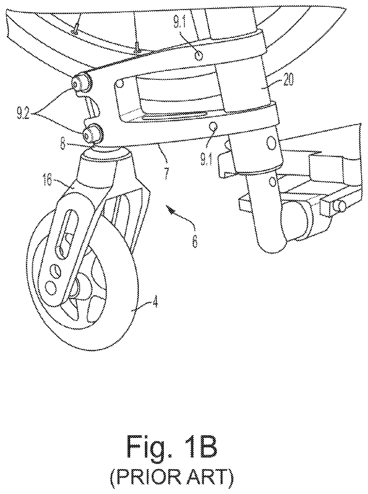
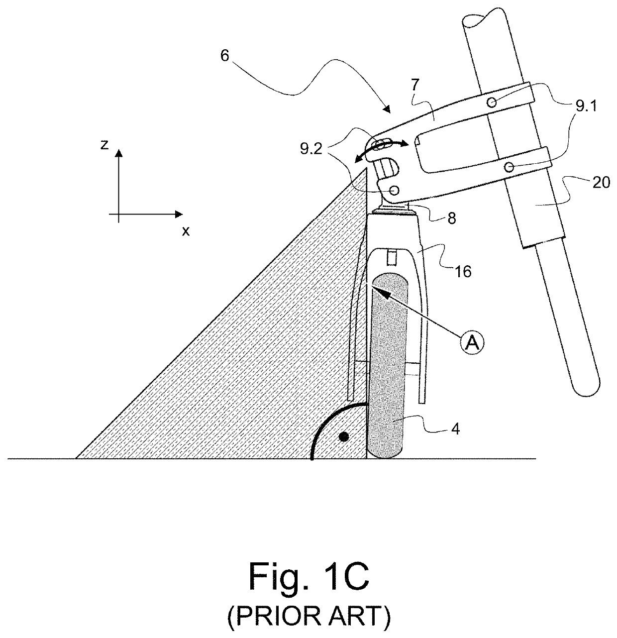
[0058]FIG. 2A is a perspective view of a caster wheel support assembly in accordance with the present invention, which caster wheel support assembly is generally designated by reference numeral 10. The caster wheel support assembly 10 generally has a first section 10A that is configured to be securable to a frame member of a wheelchair and a second section 10B that is configured to hold a swivel member 15 coupled to a caster wheel (not shown in FIG. 2A). Such a caster wheel, designated by reference numeral 4′, is depicted in the photographic illustration of FIG. 6 and can in particular be coupled to the swivel member 15 by means of a fork element 16′, in a manner similar to the known caster wheel support assembly 6 of FIGS. 1A to 1D.

[0059]A portion of a frame member, designated by reference numeral 20′, secured to the first section 10A of the caster wheel support assembly 10, is schematically depicted in dashed lines in FIG. 2A for the sake of illustration and explanation. In the pr...

second embodiment

[0081]More precisely, FIGS. 7E and 7F illustrate adjustment of the caster angle forward or rearward in the driving direction in the context of the aforementioned second embodiment of the invention. The holding member 12* is held on the frame member 20* by means the (upper) retaining element 14* and retaining element 14** in such a way as to selectively allow adjustment of the position of the holding member 12* with respect to the frame member 20* to be carried out if need be. This is achieved by configuring the retaining aperture 14C* formed in extension 12.1* to exhibit an arc shape and exploiting the (upper) retaining aperture 14A* and associated retaining element 14* as a pivot axis about which the holding member 12* can pivot after having loosened the retaining elements 14*, 14** as schematically depicted. As a result, an angle of inclination of the swivel member 15 can be adjusted forward or rearward in a driving direction, leading to a corresponding adjustment of the caster an...


PUM


Abstract

The caster wheel support assembly has a first section securable to a frame member of a wheelchair and a second section holding a swivel member coupled to a caster wheel. The caster wheel support assembly has a holding member designed as a collet configured to hold a first portion of the swivel member which extends along a first axis. A second portion of the swivel member, which is coupled to the caster wheel, extends away from the first portion along a second axis which forms an angle relative to the first axis. The first portion of the swivel member is supported by the holding member to selectively allow rotation thereof relative to the holding member about the first axis, causing adjustment of a camber of the caster wheel. The collet is configured to selectively prevent or permit rotation of the swivel member relative to the holding member.

Description

RELATED APPLICATIONS[0001]The present application claims the priority of European patent application No. 18192870.6 filed on Sep. 6, 2018, the entire disclosure of which is incorporated herein by reference.TECHNICAL FIELD[0002]The present invention generally relates to a caster wheel support assembly for a wheelchair and a wheelchair comprising the same.BACKGROUND OF THE INVENTION[0003]Caster wheel support assemblies are known as such in the art.[0004]U.S. Pat. No. 7,353,566 B2 and corresponding International (PCT) Publication No. WO 03 / 104028 A2 for instance disclose such a wheel support assembly which provides for the ability to adjust an angle of a caster wheel forward or rearward in a driving direction (referred to herein as “caster angle”). This solution is also contemplated for use as a wheelchair's rear wheel support and provide for the ability to adjust a camber of the relevant rear wheel.[0005]Further examples of caster wheel support assemblies which allow for adjustment of...

Claims


Application Information

Patent Timeline
Patent Type & Authority Patents(United States)
IPC IPC(8): A61G5/10B60B33/00B60B33/04
CPCB60B33/0005A61G5/10B60B33/0068B60B33/04B60B33/0049B60B33/0007B60B33/0023B60B33/0039B60B33/0071B60Y2200/84A61G5/1097
Inventor ZELTNER, MICHAELBRENNER, SIMONHUNIG, MARTIN
Owner INVACARE INT GMBH
Why Eureka
Try Eureka