Support with self-locking function

a self-locking and support technology, applied in the field of supporting devices, can solve the problems of long support length, occupying a lot of space, and being difficult to carry around

Active Publication Date: 2021-09-21
JIASHAN QIAOXIN ELECTROMECHANICAL CO LTD
View PDF2 Cites 0 Cited by
  • Summary
  • Abstract
  • Description
  • Claims
  • Application Information

AI Technical Summary

Benefits of technology

[0025]As described above, the second supporting rod 20 can be rotated relative to the first supporting rod 10 so as to the two first locking portion 122 is snapped respectively with the two second locking portion 222 together to achieve self-locking without manual. In addition, when folding, only the second supporting rod 20 is needed to push relative to the first supporting rod 10 so as to disengage the two first locking portion 122 with the two second locking portion 222. And at the same time as disengaging, the second supporting rod 20 is rotated. As a result, the first supporting rod 10 and the second supporting rod 20 can be folded up. Therefore, the support with self-locking function is very convenient to use.

Problems solved by technology

The Lights sometimes need to be supported by a support so as to adjust to the desired height or angle. however, in prior art, the support has a long length and takes up a lot of space and is not convenient to carry.

Method used


Image

  • Support with self-locking function
  • Support with self-locking function
  • Support with self-locking function

Examples


Embodiment Construction

[0014]The present application is illustrated by way of example and not by way of limitation in the figures of the accompanying drawings. It should be noted that references to “an” or “one” embodiment in this application are not necessarily to the same embodiment, and such references mean at least one.

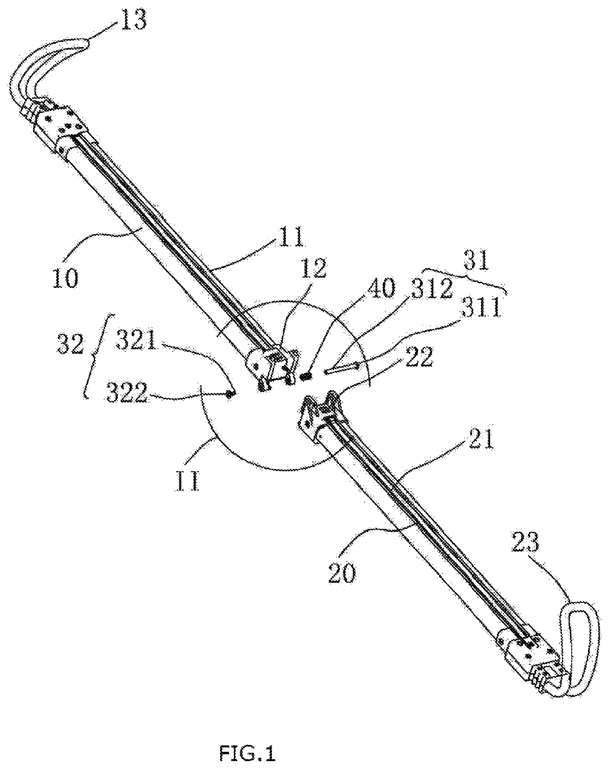
[0015]Referring to FIG. 1 to FIG. 8, a support with self-locking function is shown in accordance with an exemplary embodiment of the present invention. The support with self-locking function include a first supporting rod 10, a second supporting rod 20, a connecting portion 30, and an elastic member 40. it can be understood that the support with self-locking function may include other functional module, such as assembly component, installation component, and so on, which are well known by a person skilled in the art and not described in detail.

[0016]The first supporting rod 10 includes a first rod 11, a first locking portion 12, and a first feet 13. At least two first snap ring 111 are ...


PUM


Abstract

A support with a self-locking function includes a first supporting rod, a second supporting rod, a connecting portion and an elastic member. The first supporting rod is provided with at least one first locking hook and two rotating portions. The rotating portion has a spiral surface and is provided with a groove. The second supporting rod is provided with at least one second locking hook and a rotating portion. The rotating portion is provided with a stopper. The elastic member is sleeved on the connecting portion. The stopper is capable of sliding along the spiral step when the second supporting rod rotates relative to the first supporting rod, and is elastically pushed by the elastic member to insert into the groove. The first locking hook and the second locking hook are fastened in a snap-fit with each other, thereby realizing self-locking of the support without requiring manual locking.

Description

RELATED APPLICATION[0001]This present application is a national stage entry of PCT Application, PCT / CN2018 / 114615, filed on Nov. 8, 2018.BACKGROUND1. Technical Field[0002]The present invention relates to a supporting device, and more particularly to a support with a self-locking function.2. Description of the Related Art[0003]When performing various works at night or when there is insufficient light, such as construction in construction site, car repair, etc., work lights, ie, lights are required. The Lights sometimes need to be supported by a support so as to adjust to the desired height or angle. however, in prior art, the support has a long length and takes up a lot of space and is not convenient to carry.[0004]Therefore, it is necessary to provide a support with a self-locking function which makes it possible to solve the above problem.BRIEF DESCRIPTION OF THE DRAWINGS[0005]Many aspects of the embodiments can be better understood with references to the following drawings. The co...

Claims


Application Information

Patent Timeline
Patent Type & Authority Patents(United States)
IPC IPC(8): F16B45/00F16M13/02F21V21/26
CPCF16M13/022F16B45/00F21V21/26F16M2200/021F21V21/14F16B7/22B60Q3/35F21W2131/402F21V21/0885
Inventor CHEN, BO
Owner JIASHAN QIAOXIN ELECTROMECHANICAL CO LTD
Why Eureka
Try Eureka