Rails for a covering for an architectural opening

a technology for coverings and openings, applied in door/window protective devices, constructions, building components, etc., can solve problems such as difficult manufacturing and light passag

Active Publication Date: 2020-06-30
HUNTER DOUGLAS INC
View PDF69 Cites 2 Cited by
  • Summary
  • Abstract
  • Description
  • Claims
  • Application Information

AI Technical Summary

Problems solved by technology

Current offerings to reduce the passage of light through the connection between the head rail and the movable rail are either difficult to manufacture, are aesthetically displeasing, or both.

Method used


Image

  • Rails for a covering for an architectural opening
  • Rails for a covering for an architectural opening
  • Rails for a covering for an architectural opening

Examples


Embodiment Construction

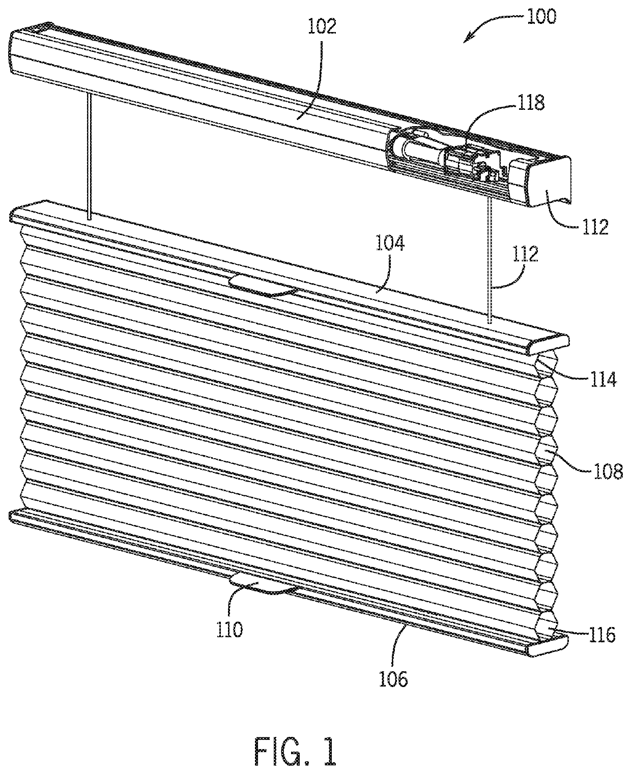
[0021]FIG. 1 is a front view of an illustrative embodiment of a movable rail utilizing at least one selectively positionable magnet assembly to releasably secure the movable rail to adjacent components of an architectural covering (e.g., to a gasket member received at least partially within a head rail of the covering). In the exemplary embodiment of FIG. 1, a covering 100 is shown in a fully extended, partially open configuration in accordance with some embodiments of the present disclosure. In one embodiment, the covering 100 includes a head rail 102, a movable rail 104, a bottom rail 106, a shade member 108 extending between the movable rail 104 and the bottom rail 106, and a handle 110 secured to at least one of the movable rail 104 and the bottom rail 106. A pair of lift cords 112 extends from the head rail 102 and is connected to at least one of the movable rail 104 and the bottom rail 106. The movable rail 104, which may be referred to as a top rail or a first rail, extends h...


PUM


Abstract

A rail for a covering for an architectural opening is provided. The rail may be attachable to a shade member of the covering. The rail may include a magnet assembly that is at least partially positioned within a retention channel formed in the rail to releasably secure the rail to a head rail. The magnet assembly may be positionable along a longitudinal axis of the rail and may include a cam lock assembly that releasably secures the magnet assembly within the retention channel of the rail. According to the present disclosure, the head rail and the rail are held in close proximity to each other to inhibit the passage of light between the rail and a head rail.

Description

TECHNICAL FIELD[0001]The present disclosure relates generally to coverings for architectural openings, and more specifically to rails for a covering for an architectural opening.BACKGROUND[0002]A movable rail typically is attached to an edge of the shade member to facilitate extension of the shade member across the opening and to maintain the shade member in a desired configuration. Some movable rails loosely connect to a head rail, which tends to permit passage of light through the connection between the head rail and the movable rail. Current offerings to reduce the passage of light through the connection between the head rail and the movable rail are either difficult to manufacture, are aesthetically displeasing, or both.[0003]The present disclosure generally provides at least one rail for a covering for an architectural opening that offers improvements or an alternative to existing arrangements.BRIEF SUMMARY[0004]The present disclosure generally provides a rail, such as a movabl...

Claims


Application Information

Patent Timeline
Patent Type & Authority Patents(United States)
IPC IPC(8): E06B9/38E06B9/266E06B9/262E06B9/323
CPCE06B9/262E06B9/266E06B9/323E06B2009/2627
Inventor SCHWANDT, MARK A.STEBENNE, MARTIN A.
Owner HUNTER DOUGLAS INC
Why Eureka
Try Eureka